![[IMAGE]](http://www.darrylsgarage.com/912/912dream.jpg)
![[IMAGE]](http://www.darrylsgarage.com/912/912OCT06.jpg)
Darryl's 1966 Porsche 912
OCTOBER 2006 PROJECT JOURNAL ENTRIES (IN CHRONOLOGICAL ORDER)
Entry: 10/2/06 - Today it was time to fabricate the replacement section of the heater tube using 2" flexible exhaust tubing. The turns within the longitudinal channel and under the torsion bar tube are too tight for the flexible tubing so I used my chop saw to make a series of cuts in the tube in order to make tighter bends. Once satisfied with the shape, I welded the cuts back up using my MIG welder. Tonight the replacement tube fits perfectly and is ready for welding into place.
![[IMAGE]](http://www.darrylsgarage.com/912/912RRKRh.jpg)
Next it was time to cut down the large replacement panel to size and fit it to cover the gaping area under the torsion bar tube left after the aggressive removal of all the rotten sheetmetal. As you can see, the patch is fitted and ready for welding in! I am amazed at how quickly the second time goes when I'm not having to ponder how I'm going to do the repair and just repeat the procedure learned on the other side. I'm thinking I'll be installing the new floorpans in once the longitudinal panel is finished on this side and then finish up with the rockerpanel.
![[IMAGE]](http://www.darrylsgarage.com/912/912RRKRi.jpg)
Entry: 10/3/06 - Before I can weld in the outer longitudinal patch panels, I've got to finish up a couple small tasks inside the channel. First of all was replacing the rotted-away outboard seat rail support rib. There is a small corrugated reinforcing rib welded under the seat rail that is designed to keep the seat from flexing the inner longitudinal panel sheetmetal under the occupant's weight or hard cornering. I cut off the old one and traced the corrugation pattern onto a paper pattern so I could bend a new one out of 20-gauge sheetmetal stock. Once bent, I cut it to match the profile of the floorpan and welded a 10 mm wide "foot" on it so it lays flat against the floorpan sheetmetal. I'll probably add a very thin strip of 3M strip caulk or seam sealer to the bottom of it when I put the floorpans in just to keep it from attracting moisture and rusting again.
![[IMAGE]](http://www.darrylsgarage.com/912/912RRKRj.jpg)
Once the seat rail reinforcing rib was welded in using the holes I punched in it for plug welds, my attention turned to welding in the new heater tube section. I welded some small tabs on to the old heater tube anchoring fixtures where the old welds were and tack welded the new tube onto the tabs and in several spots where the tubes mated.
![[IMAGE]](http://www.darrylsgarage.com/912/912RRKRl.jpg)
The last step was using "Muffler Patch" sealing paste to seal the mating point where the old tubes and new tube meet. I chose "Muffler Patch" because it would hold up to high temperatures without breaking down or smelling like something was melting. A thick coat of black Eastwood's Rust Encapsulator inside the channel and over the heater tube completed all the work that needs to be done inside the longitudinal. I media blasted and painted the rear suspension components to fill the last hours of work for the day. The next step is welding on the patch panels and closing that longitudinal panel!
![[IMAGE]](http://www.darrylsgarage.com/912/912RRKRk.jpg)
Entry: 10/4/06 - Today it was time to close up the right longitudinal, starting the welding with the patch panel under the rear torsion bar and ending with the inner rocker panel pressing. A little final fitting and a couple hundred spot weld puddles later and it's all together, solid as a rock. I'm always amazed at how ugly my welds look because they're spot welded puddles and not a continuous bead. I'm always pleased with the penetration of each weld and after grinding to dress them, they'll look perfect. Dressing will have to wait for now as I'm excited to see how accurate my measurements have been. Now for the million dollar question, "Do all the new spotweld flanges I've added line up with the new floor pan pressings, especially under those rear torsion bar tubes?" Well, to find that out I needed to use every one of my Vise-Grip pliers and slowly work the replacement floor pans into position. The answer to the million dollar question? YEAH BABY! PERFECT-O!!!
![[IMAGE]](http://www.darrylsgarage.com/912/912flor6.jpg)
I still need to figure out how I'm going to knit the front seam of the front floor pan pressing into the existing pedal mounting points and such and today's fitting allowed me to mark-off the precise locations of those mounting points. Otherwise the rest of the flanges around the perimeter of the floorpan are very, very close! I can really picture how this is going to look all welded in and covered with a 1/8" thick coating of sound deadener on the cabin side and thick splatter coat of undercoating on the outside. I don't think anybody will be able to detect the repair without having the subtle differences in the replacement pressings pointed out to them, as is the intent.
![[IMAGE]](http://www.darrylsgarage.com/912/912flor7.jpg)
Entry: 10/6/06 - Today the dirty job of grinding down my ugly longitudinal panel welds into beautiful flush ones was the task looming in front of me. It took about a solid hour of grinding, first with my 4�" grinder and finishing with my Dremel tool in the tight spots. As you can see in the following picture, the welds are ground flush and any high spots have been hammered down flush to create a smooth seam line.
![[IMAGE]](http://www.darrylsgarage.com/912/912RRKRn.jpg)
Trimming the excess upper weather strip lip off the replacement outer rocker panel pressing was required to test fit it and the longitudinal support (the cone shaped thing just behind the lockpost). The test fitting went quite well and it looks like things are going to go smoothly when I get to that point in the restoration.
![[IMAGE]](http://www.darrylsgarage.com/912/912RRKRp.jpg)
I want to put the freshly media blasted and repainted rear torsion bar and spring plate back in next so I had to patch the undercoating I removed above the welds for the new sheetmetal. First by hand "dabbing" 3M Ultrapro Autobody Sealant to emulate the random splatter pattern of the original factory undercoating... a slow and tedious task, making sure not to get too close to the bottom pinchweld flange that still needs to be welded.
![[IMAGE]](http://www.darrylsgarage.com/912/912RRKRm.jpg)
Once the 3M seam sealer had dried, it was time to give it a couple thick coats of Wurth high-build underseal, blending in with the original factory undercoating. It seems like my skills at this undercoating blending get better with each time I get to practice the craft. With the quarter panel welded back on and the wheel and tire mounted, I do believe it will be impossible to detect a patch has been made! There is no body filler so there's no magnet detectable evidence of repair.
![[IMAGE]](http://www.darrylsgarage.com/912/912RRKRo.jpg)
Entry: 10/7/06 - Today a new Porsche friend, Charlie C. stopped by to talk Porsches, see my rust repair efforts close-up and have me help him estimate the rust repairs required on his '69 911E. I'm always happy to pass along any knowledge I can to help with saving one of these wonderful old cars. Once Charlie left, I began the installation of the restored right rear suspension. The splined torsion bar is kind of a puzzle to figure out in order to get the spring arm to align at the right angle. I figured it out through trial-and-error but the technical manual spells it out pretty straight forward; 40 splines on the inboard end, 44 splines at the outboard end, one spline change inboard = 9�, one spline change outboard =8�10'. All this dinking around with the torsion bar ended-up with the ride height restored to its original position on my 912 and all the freshly repainted suspension components bolted back in with new rubber bushings installed. I will be needing to have the front and rear wheels aligned once the car is all back together but the ride height is back to the "high" original factory position.
![[IMAGE]](http://www.darrylsgarage.com/912/912RRKRq.jpg)
The rear brake discs are like new (right at 10 mm thick) and have been media blasted and sprayed with a coat of spray on galvanizing (zinc) paint. I will have the braking surface given a "dressing cut" at the machine shop when I'm ready to install new calipers. Once I got all the rear suspension stuff sorted out and bolted in, I put the road wheels back on the rear axle and lowered the car off the jacks so I could use them to push the rear floor into its highest position. I found a really great picture of the finished rear floor and longitudinal panel flanges the way they came from the factory so I can determine how much of the excess flange I need to cut off and roll over on my replacement ones. I think I can make mine look just like factory, no worries!
![[IMAGE]](http://www.darrylsgarage.com/912/912exam1.jpg)
![[IMAGE]](http://www.darrylsgarage.com/912/912flor8.jpg)
I have quite a bit more metal to remove from the rear bulkhead flange at the back end of the center hump before the new floorpan can be pushed high enough to touch the spotweld flanges along the inside perimeter. Just one of the dozens of details that need to be worked-out before I can weld the floor in and all very exciting to be at this point and picturing that floor finished.
Entry: 10/9/06 - Today it was time for some "spelunking" in the center tunnel. I carefully removed the hand brake and cables, shifter and throttle linkage, and speedometer cable to see what kind of condition they are in. I made a big order to Stoddards to get the rest of the new bushings, rubber boots and a new brake line kit to complete the job. I could probably do without replacing the brake lines but what better time to replace the one inside the center tunnel than now with the floor out. The fuel line looks to be in perfect shape so that will be left as is. I turned my attention to how I'm going to attach the front edge of the new front floorpan, saving the original reinforcing plate for attaching the base of the gas pedal. As you can see in the following photo, I used red-oxide primer to "ghost" where the new floorpan will be slipped on top of the gas pedal reinforcing plate and plug-welded to the old one through the holes I punched there. The two large holes are for accessing the captive nuts to hold the foot pedal down. I also punched plug-weld holes all the way across the front lip of the new floorpan for attaching it to the �" overlap I left in the original floorpan. I decided plug welds would be easiest from the bottom side because I can use my screw jacks to press the new floorpan sheetmetal up to the old floor, which has already been stripped and primed with zinc 3M Weld-thru Primer.
![[IMAGE]](http://www.darrylsgarage.com/912/912flor9.jpg)
Working out the details of the rear edge of the rear floorpan where the rear bulkhead of the center tunnel attaches was fairly easy to figure out. The original factory weld was a bead along the edge of a flange on the rear tunnel bulkhead pointing rearward where the bulkhead and floorpan sheetmetal meet. All I had to do was cut away the weld and the original floorpan sheetmetal peeled away to provide a nice clean edge to align the new floorpan sheetmetal to. I'll have to cut the excess lip off the new pressing to make it easier to form to the contour of the rear bulkhead under the shift rod hole. Removing all the cables and throttle rod is required so I can have access to that lower edge with my MIG welder. I don't think I need to remove the heater control cables since they sit high enough to be out of the way. I have a little surface rust to spot sandblast on the last 10" or so of the inside of the center tunnel spotweld flanges where water pooled but was caught before it could weaken the sheet metal there.
![[IMAGE]](http://www.darrylsgarage.com/912/912flora.jpg)
The final task for the day was to cut down all the new pinchweld flanges around the perimeter of the new outer longitudinal sheetmetal to its final size. Once cut down, plug-weld holes were punched every �" (the same distance apart as the factory spot welds) along the perimeter pinchweld flange and the inside longitudinal panel to floorpan flange. I plan to position the new floorpans so the top edge of the flanges line up, make the plug-welds and then cut off the excess sheetmetal from the bottom edge of the floorpan flanges. I may or may not run a solid bead of weld along the bottom edge before I cut off the excess, depending on how solid the pans feel with the plug-welds.
![[IMAGE]](http://www.darrylsgarage.com/912/912RRKRr.jpg)
Entry: 10/10/06 -Today's efforts focused on preparing the spot weld flanges on each side of the center tunnel. I had been considering leaving the extra layer of original floor spotwelded to the flange but the double thickness of metal made it impossible to punch with my pneumatic plug-weld punching tool. It also left the possibility of rust lurking between the layers of old spotweld flange which isn't acceptable so I decided to bite the bullet and remove it. Peeling back the old floorpan steel spot welded to the flange took several hours but when it was all removed, I punched the plug-weld holes with my tool and all was good. I also prepped the flange on the interior wall of the rear floor bulkhead and punched the plug-weld holes there as well. Once all traces of surface rust was removed from the bottom side of the center tunnel spot weld flange, surface rust inside of the tunnel and asphalt based undercoating from the rear side of the rear floor bulkhead, I sprayed it with a coat of zinc 3M Weld-thru Primer and declared it ready to weld. The longitudinal flanges need the bottom sides cleaned and primed but I ran out of primer so that will have to wait.
![[IMAGE]](http://www.darrylsgarage.com/912/912florb.jpg)
Now for the fun stuff, final fitting of the front floorpan pressing. I little trimming up front around the pedal area and then forming it with a blunt-ended chisel attachment for my air hammer and it fit in very nicely. Any remaining gap fitting around the pedal area can wait until after the plug-welds are done and I can form and knit the new pressing into the old for a more finished look. As it sits right now, all the spotweld flanges mate perfectly and when dressed to expose the bare metal at all contact points, will be ready for welding. I need to complete the right jack plate installation before starting with the rear floorpan fitting, so that will be the next task.
![[IMAGE]](http://www.darrylsgarage.com/912/912florc.jpg)
Entry: 10/11/06 - Another new Porsche friend, James S. stopped-by today to have me take a look at his beautiful '81 911SC coupe and get my recommendations on some problem areas. It really reminded me of my first 911, an '81 911SC targa and that whole wide rear tire, flared rear fender, whale-tail phase I went through about 10 years ago, funny but now I'm into the older narrow bodies. Today's project was attaching the right jack plate and tube. The pressing for this piece from Restoration Design is not quite the same shape as the original one. With some flattening in my shop press and reworking of the bend at the bottom with a couple cuts and hammering, I was able to replicate the look and fit of the original. After welding the jack tube into position on the inner rockerpanel and anchoring it with a weld to the interior longitudinal panel, I punched plug-weld holes around the perimeter of the jack plate and welded it into place. A weld bead around the sides and bottom of the tube to attach it to the jack plate, dressing the welds that show once the outer rocker panel is installed and some 3M Weld-Thru Primer and I was done. Now I can start fitting the rear floorpan pressing next.
![[IMAGE]](http://www.darrylsgarage.com/912/912jack1.jpg)
![[IMAGE]](http://www.darrylsgarage.com/912/912RRKRs.jpg)
Entry: 10/12/06 - Today's efforts got off to a slow start. I began the day with doing some media blasting and discovered that my dust collector was plugged because my media is getting too dusty from too many trips through the blaster. The first couple hours were spent disassembling the dust collector and washing out the filter bag with a garden hose. I'll be emptying the old media from the cabinet and getting new stuff on Monday. After that "housekeeping" task was completed, I welded in the left side jack tube to the anchor point on the inner longitudinal panel and began fitting the rear floorpan pressing. After hours of very hard labor, the rear floorpan pressing has been coerced by hand and air hammer into the final position and the flanges all formed so the 90�bends align like a 'T' on the pinch weld flanges along the rockerpanels and the flanges make uniform contact along the floor flanges. I'm still waiting on welding the pans back in until my Stoddards order with the new parts for inside the tunnel arrives and in the meantime will be wire-brushing all the flanges and zinc priming them in preparation for welding day. Tomorrow is a big day for me, I finally get to take my '63 VW Beetle Cabriolet in to have a new top custom made by Steve Shepp, one of the best German car trimmers on the West Coast! It's taken a year to get this spot in the long line that has formed in front of his door and his last project was a hand-build 1953 Graber Bentley roadster insured for over a million bucks!
![[IMAGE]](http://www.darrylsgarage.com/912/912RFLR1.jpg)
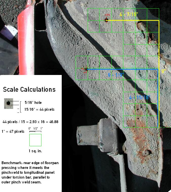
Entry: 10/13/06 - There are some factory drain / access holes in the floorpan and longitudinal panels that are plugged with the same little rubber plugs as those used in the floor of the center tunnel. Since rust had obliterated where they were on my original sheetmetal, some investigation was required and luckily, a few months back, I snapped a digital photo of an intact '66 912 rear clip resting on its top at my friend Jack Morris' boneyard behind his shop, Wolfsburg Motorwerks in Ballard. Some careful manipulation in Photoshop and plotting using pixels as the measuring unit, I was able to plot their precise locations in inches. Tomorrow, I'll drill those holes, and the 3 others that run down the side of each inner rocker panel so I can access those body cavities with rust proofing materials once the floorpans are all welded in. Double-click on the following photo to see the full-size (readable) hole location map.
Entry: 10/14/06 - The front and rear floorpan pressings have all the pre-welding fitting and trimming done and as you can see in the photo below, the center seam mates exactly as it will once installed in the car, rear floorpan first. Today I also drilled all the factory drain / access holes that will be used to rust-proof the longitudinal body cavities once the welds have been completed. It was a very good thing to do the drilling while I could still have access to the inside of the longitudinal channel and shield the heater tube from punctures with the drill. I double-checked the hole size on the inner rocker panel access holes and discovered they are slightly smaller than the holes in the center tunnel and I adjusted the size accordingly. I've made significant progress on wire brushing the remaining plug-weld flanges in preparation for welding. Next I need to repair the broken weld on the left parking brake tube inside the center tunnel. I'm taking my time and trying to anticipate everything that needs to be considered while waiting for the Stoddard's part order and the actual welding of the pans... no reason to be in a rush but quite exciting to think this major phase is nearing completion!
![[IMAGE]](http://www.darrylsgarage.com/912/912flord.jpg)
Entry: 10/16/06 - Most of the morning was spent driving down to Kent to pick-up four 80 lb. bags of 80-grit aluminum oxide blasting media and driving up to Everett to pick-up a few more cheap vise-grips for the big floorpan welding job from Harbor Freight Tools. Once I got back to work in the shop, the focus was on getting the remaining plug-weld flanges prepped for welding. Just about the time I was finishing the last flange and started on repairing the broken parking brake tube, that familiar sound of the UPS truck's horn honking alerted me to a delivery. YES!!! The Stoddards order arrived with the new parts I need to install in the center tunnel before I can commence with welding in the pans!!!
![[IMAGE]](http://www.darrylsgarage.com/912/912pbrk1.jpg)
Fixing the parking brake tube first required cleaning all the grease out of it so it wouldn't catch fire with the welding. It took 6 passes with clean cloth swabs soaked in carb cleaner, pulled thru like a gun cleaning patch on a length of wire. I wire brushed the area to be welded and discovered it had been brazed before so instead of MIG welding it, I got out the oxy/acetylene torch and added some more flux and brass to the cracked mounting bracket. It was a bit difficult brazing upside-down but I was able to form a nice drip that reinforced the cracked area and declared it done. I removed the old brake line, able to save the rubber plugs that run through the front and rear bulkheads and ran the new one without the rubber plugs until after welding is done. I was going to run the new speedometer cable but fear that I might damage it during the floorpan welding so it must wait. I finished by installing the new throttle rod bushings and the throttle rod. I do believe that everything is good-to-go for welding in the new rear floorpan in the morning!!!
![[IMAGE]](http://www.darrylsgarage.com/912/912pbrk2.jpg)
Entry: 10/17/06 - Today's work was interrupted with a call from the Honda dealership informing my wife that the new 2007 CR-V she had ordered to replace her car we totaled last month had arrived so we had to go take delivery. With the interruption, I was only able to get the rear pan about 95% welded-in and still need to weld the area at the rear edge of the center tunnel from the underside. The plug-welds went in quite cleanly and I'll only need to dress the ones visible from the outside of the car. The unibody rigidity of the rear section is amazingly drum-like and I'm anxious to see the additional improvement when I get the front pan welded in.
![[IMAGE]](http://www.darrylsgarage.com/912/912RFLR2.jpg)
I lost count at about the 100th plug-weld!
![[IMAGE]](http://www.darrylsgarage.com/912/912RFLR3.jpg)
Entry: 10/18/06 - Tonight the new floorpans are welded in with only a few seams on the bottom and around the pedal area to complete. Everything fit perfectly and with a bit of trimming and air hammer work up front, blended in with the original pan very nicely. The floors respond with a nice low thud when I drum on them with my fist.
![[IMAGE]](http://www.darrylsgarage.com/912/912florf.jpg)
The last step is fitting the small pressings on the inside torsion bar area that covers the still visible flexible heater tubing patch. The repair kit I bought from Stoddards for the area around the torsion bar tubes came with the sheetmetal pressing for that area so I'll be able to replicate all the details of the original. I have a lot of plug-welds to dress with my grinder all the way around that lower rockerpanel edge but it sure feels great to be nearing completion of this phase.
![[IMAGE]](http://www.darrylsgarage.com/912/912flore.jpg)
Entry: 10/19/06 - Today I completed all the remaining welds, the most significant of which was the weld at the floor of the center tunnel where it meets the rear bulkhead. The factory weld was a bead where the two sheets of steel lay on top of each other. I thought it would look most factory if I used my oxy/acetylene torch and steel rod, so that's how I proceeded. Here's how it looks all welded up and primed, just like the original did!
![[IMAGE]](http://www.darrylsgarage.com/912/912florh.jpg)
Once I put the welders away, it was time to start grinding plug welds. I was able to get the driver's side rockerpanel pinch weld seam completed and here's how it sits tonight. I'm going to be grinding for several days to get everything done but it sure makes me happy to see more sections coming to completion!
![[IMAGE]](http://www.darrylsgarage.com/912/912florg.jpg)
Entry: 10/20/06 - Today's task was taking the inner longitudinal channel patch panels, which came with the kit I purchased from Stoddards, and trimming them to fill the void I cut away to remove all the traces of rust. I wanted to make sure the circular indentation found on the originals was retained in the patch.
![[IMAGE]](http://www.darrylsgarage.com/912/912flori.jpg)
Tonight the patch panels have been snipped and formed down to size and are clamped in place ready for welding in the morning. I also have a small patch to weld into the driver's side rear corner of the floor bulkhead, which was rusted on one side but not the other. Once they are all welded in, I can give the entire area the "faux factory undercoating" treatment like I did around the torsion bars and move on to grinding more plug-welds. I was sore today from all the grinding I did yesterday... luckily I have the 4-post lift so all the grinding was at chest level instead of laying on my back on the ground! Guess I shouldn't bitch too much, eh? :^D Oh and yes, those round things on the banana arms in the following photo are plastic rattle-can lids... those brake hose retaining tangs are damn sharp and right about forehead high... can you say, "HEAD-ON, APPLY DIRECTLY TO THE FOREHEAD!" That and put the plastic caps on them so you only have that unpleasant experience only once!
![[IMAGE]](http://www.darrylsgarage.com/912/912florj.jpg)
Entry: 10/21/06 - Today's job was welding in the patch panels for behind and under the rear torsion bars. I wasn't completely happy with the left side so I re-worked it a bit to keep things perfectly symmetrical with the right one. I also welded in the small corner patch where the left rear floor bulkhead meets the longitudinal and floorpan panels. Once the welding was completed, I dressed the welds and blended in my "faux factory undercoating" to where I had left off on the left side, since I have already completed dressing the entire rockerpanel flange welds. You can see today's new plug-welds visible on the right side patch panel in the background of the following photo.
![[IMAGE]](http://www.darrylsgarage.com/912/912LLNG1.jpg)
Once the finger-tip "dabbed" 3M Ultrapro Autobody Sealant has dried, I'll be giving it 2-3 thick coats of Wurth high-build underseal as I've done on the other areas of the car. As you can see in the following photo, the merging of the seams for the floor, rear cabin floor bulkhead and longitudinal panel looks just like factory original. The thick coating of the 3M seam sealer replaces the nasty asphalt coating I scraped-off to prep for the welding. I also patched the undercoating on the torsion bar tube where some jack scrapes had rubbed through the original coating. With the overcoat of Wurth High-Build Underseal, this should blend back in nicely with the remaining factory original undercoating.
![[IMAGE]](http://www.darrylsgarage.com/912/912LLNG2.jpg)
Entry: 10/22/06 - Dressing the plug-welds on the entire right rockerpanel flange and the inner panel under the right torsion bar was the first task for the day. Once that task was completed, it was "faux factory undercoating" time for those areas.
![[IMAGE]](http://www.darrylsgarage.com/912/912RLNG1.jpg)
The patch was somewhat smaller on the right side so while not exactly a mirror image of the 3M Ultrapro Autobody Sealant application, all the same areas given the treatment as I did on the left side yesterday. I'll be removing the rear suspension banana arms again when I spray on the Wurth high-build underseal, so I can give the areas around their mounting brackets a thin coat to dress the area up. I would like to preserve as much of the original undercoating as possible so I'll be masking off large sections around the rear seat pans so the overspray doesn't mar their original appearance. I'll be dressing the welds visible inside the cabin, such as around the foot pedals and giving all the weld flanges a thick coat of 3M Seam Sealer as my next area of focus.
![[IMAGE]](http://www.darrylsgarage.com/912/912RLNG2.jpg)
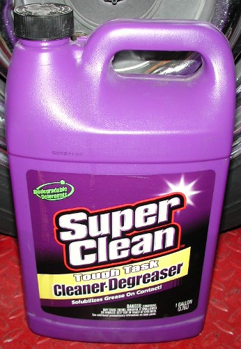
Entry: 10/23/06 - Time to finish the "faux factory undercoating" on the rear longitudinal area. I removed both side's rear suspension banana arms plus the brake lines and pulled any wiring harness, fuel line and heating cables out of the retaining tabs so I could use my favorite purple "SuperClean" biodegradable degreaser and scalding hot water to prep the areas under them for a coat of Wurth high-build underseal. After masking off the areas I didn't want to spray with newspaper and aluminum foil, several thick coats were applied. I masked-off the floorpan because I'm planning on using anther Wurth undercoating product on them, which will form factory style drips with the help of gravity, something I can't do on the vertical surfaces that receive the "faux" treatment. Tonight the underseal is drying in the heat of two 500-watt halogen spotlights. I consider this area pretty much finished and ready for final installation of the suspension, speedometer cable, new seals and brake lines.
![[IMAGE]](http://www.darrylsgarage.com/912/912RFLR4.jpg)
Entry: 10/24/06 - Finishing the undercoating and performing final assembly of the rear suspension area was the goal for today. I gave the wheels and tires a thorough cleaning and bolted everything back into place with careful touch-up of painted parts that had been oversprayed or scraped. Once everything was back in I sprayed the entire area with clear high-temperature engine enamel to freshen-up the surfaces and make them shine. I started putting the new rubber control bellows on where they come through the rear center tunnel bulkhead, all but the speedometer cable. Suffice to say, I'm pretty stoked with how all this went back together and to have finally finished this section.
![[IMAGE]](http://www.darrylsgarage.com/912/912done2.jpg)
![[IMAGE]](http://www.darrylsgarage.com/912/912done3.jpg)
The last half of the day's labors went into grinding down all the welds on the bottom side of the front floorpan and dressing the seams with 3M Ultrapro Autobody Sealant. I textured the seam sealer with my "faux factory undercoating" fingertip dabbing method to even out the surfaces where the seams are lapped over each other. I'm ready to start with the inside floorpan work next, which will focus on dressing the welds up around the pedal area and sealing the seams with 3M Seam Sealer prior to applying the QuietCar soundproofing material.
![[IMAGE]](http://www.darrylsgarage.com/912/912flork.jpg)
Entry: 10/26/06 - Preparing the interior floorpan for soundproofing was the focus of my efforts the last couple days. My first task was to grind all the welds, first with minimal dressing of the plug welds since they'll be hidden by seam sealer and the spray-on soundproofing. The welds around the pedal area were fully dressed to the point where the seam is not visible. A quick media blast of the rust scaled pedal cluster base and a test fit into the floorpan confirmed that none of the new welds interfered with the controls. Once the weld dressing was complete, I thoroughly vacuumed and blew the grinder dust out of all the recesses and gave the seams a liberal coat of SEM Rust Seal to stabilize the metal around the weld areas. After letting the SEM Rust Seal dry overnight, I prepped the entire floorpan for painting with a ScotchBrite pad soaked in DuPont KwikPrep 244S solvent. Once the KwikPrep dried, with the help of some compressed air, I brushed-on a thick coat of black Eastwood's Rust Encapsulator which, as you can see in the following photo, is in the process of drying with the help of two 500-watt halogen lights under the car which raises the surface temperature of the floorpan to about 80�. All the metal is now sealed with a waterproof (rustproof) barrier for the soundproofing material to be applied upon.
![[IMAGE]](http://www.darrylsgarage.com/912/912florl.jpg)
Once the Rust Encapsulator has dried thoroughly, I'll apply 3M Ultrapro Autobody Sealant to the weld joints to keep any moisture from the water-based soundproofing material from getting between the layers of steel. The areas around the pedal cluster and seat track mounting points and the top side of the center tunnel where the parking brake and gear shift is mounted will be masked-off before the QuietCar soundproofing material is sprayed on using my Wurth undercoat application "shutz gun" in 3 coats over the main floorpan area. I also need to decide how I'm going to seal the floor of the center tunnel. I'm thinking about thinning the Eastwood Company Rust Encapsulator so I can spray it into the cavities and let the excess drain out the floorpan drain holes.
Entry: 10/28/06 - After a day of curing over the heat of two 500-watt halogen lamps, the thick coat of Eastwood's Rust Encapsulator had hardened enough for a liberal application of 3M Ultrapro Autobody Sealant to the weld seams. I've decided to finish all welding on the right outer rockerpanel and lockpost before applying any soundproofing because of the possibility of the heat from the welding adversely affecting the bond of the QuietCar soundproofing material.
![[IMAGE]](http://www.darrylsgarage.com/912/912florm.jpg)
The first step in the attachment of the outer rockerpanels is test fitting the front fender to determine the location of the gap of leading edge of the rockerpanel where it meets the rear edge of the fender. Before I could test fit the fender, I needed to use my propane torch, scraper and wire brush to remove the dried fender sealing tape from the mating surfaces. I was delighted to find that this used right fender, from the extremely rusty '68 912 donor front clip, was actually more solid than the left one, upon which I had to do extensive patching of the fender flange. There are a couple rotten areas on the fender flange that will require some small patches but no major fabrication effort. The lower rockerpanel area looks like it would be a good idea to cut out the rusty inner section to see how close to bubbling though the rust is on the outer surface. From the looks of it, I would speculate that it is going to need to be patched to the same extent as the left one was, just to insure no future rust bubbles in that problematic area.
![[IMAGE]](http://www.darrylsgarage.com/912/912RFND1.jpg)
Once the front fender was bolted on securely, it was time to test fit the door. The sheetmetal gods were smiling on me, check out the uniform gaps on the front and rear of the door, showing that there was no body sag whatsoever during my longitudinal channel reconstruction! I may need to shim the door hinges with a 1mm spacer to achieve a uniform 3mm gap front and rear as now it appears to be 4mm in the rear and 2mm in the front. The hood to fender gap is a uniform 3mm all the way down, thanks to some subtle coercion from sledge hammer and a wood block of 2x4! The outer rockerpanel pressing is held to the weatherstrip channel with three sheetmetal screws and the wood supports press it flush with the inner rockerpanel. It's already a uniform gap at the bottom of the door, once again thanks to the trusty sledge hammer and wood block treatment.
![[IMAGE]](http://www.darrylsgarage.com/912/912RRKRt.jpg)
