![[IMAGE]](http://www.darrylsgarage.com/56oval/56vwlogo.jpg)
Darryl's 1956 Volkswagen Oval Window Beetle
Project Page
Last Updated on September 18, 2022
UPDATE: 9/18/22 - Last summer I purchased a set of reproduction oval window fenders from KlassicFab (the green patch panel people). I attempted to fit them to the car and was less than pleased with how poorly they fit. The fit where where the front edges of the fender met rear quarter panel flange was terrible and the gap was big enough to stick my pinkie finger in. The rear bottom edge was also about an inch too short. This summer I saw that Wolfsburg West was selling the German-made Blech-Manufaktur reproduction early rear fenders for about twice the price of the KlassicFab fenders. I really didn't want to spend weeks reworking the KlassicFab fenders so figured the extra cost was worth it if they fit. Well after a SNAFU with Wolfsburg West sending two right fenders which was quickly resolved by their excellent customer service, I soon had a left and right and did a test fit. All I can say is WOW! The German-made ones are such an improvement over the green KlassicFab junk, especially how perfectly the rear edge meets the bottom of the rear apron with the perfect curve that will require absolutely no adjustement. I will have to drill the bumper overrider support bar holes but that's easy with some careful measurement and a step drill. The thing that kills me is the cheapo Brazilian repros I originally purchased fit perfectly the first time, go figure! My 914's unexpected dropping of an exhaust valve seat and the resulting decision to completely restore the underside of the car to "like new" while the engine was out over the winter as well as dealing with a problem with my 912 suddenly running rough and plugging the carburetors with soot that I'm still working of resolving has pushed the poor oval window back into the showroom and waiting for someday when the Porsches are all happy again.
![[IMAGE]](http://www.darrylsgarage.com/56oval/56rfend1.jpg)
![[IMAGE]](http://www.darrylsgarage.com/56oval/56rfend2.jpg)
![[IMAGE]](http://www.darrylsgarage.com/56oval/56rfend3.jpg)
![[IMAGE]](http://www.darrylsgarage.com/56oval/56rfend4.jpg)
![[IMAGE]](http://www.darrylsgarage.com/56oval/56rfend5.jpg)
![[IMAGE]](http://www.darrylsgarage.com/56oval/56rfend6.jpg)
UPDATE: 9/10/21 - Summer "welding & grinding season" when I can work with the doors open is coming to an end. Because of being hindered with some back pain issues and more unexpected work on my other cars my pace of work has slowed, I haven't made quite as much progress as I had hoped on the old Oval. I do have the hood test mounted on the car and I'm very pleased with the passenger side, the driver's side still needs quite a bit of massaging on the lower edge to hug the curve of the opening better. I did make some great enhancements to my body dolly by making the wheel track wider so I can easily roll it on and off my 4-post lift with the wheels centered on the deck. I also converted the tires on the dolly from innertube pneumatic (and leaking rapidly) to solid rubber so it rolls so much easier, allowing me to move it in and out of the shop with much less effort. I also purchased some KlassicFab 18-gauge rear fenders for the car which I've got to say I'm not impressed with the fit and they will require a significant amount of rework to make right.
I've decided my winter project will be upgrading the engine in my 1974 Porsche 914 by converting the now Weber 40 IDF carburated 1.8 liter motor to 2.0. This should be a pretty fun project considering most of problems are already solved and it's simply a matter of removing and reinstalling the engine once the mechanical upgrades are finished by my good friend Jack Morris in Spokane. I will also be dropping off the "tunnel" transmission for the Oval off with Jack for a rebuild using a Type 2 nosecone so the mounts fit the Oval's pan.
![[IMAGE]](http://www.darrylsgarage.com/56oval/56hood9.png)
UPDATE: 9/8/21 - Over the last couple months I've finally gotten back to finishing the remaining sheetmetal work on the old Oval. The hood was really a hot mess once I could take a good look at it after having it media blasted. It turns out that it's not a factory 18-gauge hood but rather an aftermarket 22-gauge one. It was also full of BONDO covering lots of ham-handed repairs to the customary crack near the hood support arm and cracks and rot at the bottom that left "lace" metal so thin the only way to repair it correctly was cutting out a large section and welding in a patch using 22-gauge sheet metal to match the thickness. The outer lip is actually two layers of 22-gauge sheet metal spot welded together so replacing an inner section that was cracked in so many spots, welding up those cracks would never hold up to the flexing these hoods have to go through. My solution was forming a new inner lip section out of 1/8" strap metal and welding that in so it's all nice and solid. A couple "relief" cuts were required to create a uniform gap with the new rubber weatherstrip installed to see how it looks on the car. The areas around the hood handle were cracked too so that whole section needed to be welded back up. Now it feels very solid as I raise and lower it so the hood is ready for a little filler to cover the welding scars and then a protective coat of the etching primer like the rest of the completely media blasted body is wearing.
![[IMAGE]](http://www.darrylsgarage.com/56oval/56hood1.png)
![[IMAGE]](http://www.darrylsgarage.com/56oval/56hood2.png)
![[IMAGE]](http://www.darrylsgarage.com/56oval/56hood3.png)
![[IMAGE]](http://www.darrylsgarage.com/56oval/56hood4.png)
![[IMAGE]](http://www.darrylsgarage.com/56oval/56hood5.png)
![[IMAGE]](http://www.darrylsgarage.com/56oval/56hood6.png)
![[IMAGE]](http://www.darrylsgarage.com/56oval/56hood7.png)
![[IMAGE]](http://www.darrylsgarage.com/56oval/56hood8.png)
UPDATE: 2/24/14 - The tach came back from North Hollywood Speedometer today and I'm a happy camper. Other than a tiny bit of the numbers overlapping the idiot lights, it turned out awesome! The black bezel tucks in behind the black lighting ring used inside the VW speedometer that serves as an inner bezel to center the instrument in the chrome speedometer bezel which attaches to the dashboard. The color of the idiot lights is perfect '56 vintage style! I can't wait to see it in the dashboard, Photoshop will have to suffice for now!
![[IMAGE]](http://www.darrylsgarage.com/56oval/56tach8.jpg)
![[IMAGE]](http://www.darrylsgarage.com/56oval/56tach9.jpg)
UPDATE: 2/15/14 - The need to use the 7000 max RPM 6-volt electric 356C tach on my twin-plug 356C project caused me to rethink my Okrasa project's needs. Through some horsetrading, I scrounged up a perfect 6-volt 6000 max RPM tach which is the same size as the one I mounted in the Bug speedo case. I also found a photo of the perfect vintage looking Pre-A 4500 RPM dial layout on the internet. A little Photoshopping to move things around and draw in the '56 VW's idiot light layout (choosing to delete the hi-beam indicator) and I soon had a "thousand word" description of my desires for an e-mail and phone discussion with North Hollywood Speedometer's guru Hartmut Behrens. I shipped off the instrument and will be waiting to hear more once they evaluate it but I'm thinking this is just a simple silkscreening and instrument restoration project.
![[IMAGE]](http://www.darrylsgarage.com/56oval/56tach6.jpg)
![[IMAGE]](http://www.darrylsgarage.com/56oval/56tach7.jpg)
UPDATE: 12/15/13 - I retrieved the front hood, front fenders and doors from the blaster and got them home without any exposure to rain. Next I gave them a thorough rinse with Eastwood's Metal Wash phosphate etching solution to retard flash rusting and stored them in the climate-controlled showroom until I'm ready to start work on them. I was actually quite amazed at how little damage there will be to straighten prior to filling and skim coating. Unfortunately, the metalwork is on hold, I've been distracted by a new Porsche dangled in front of my nose, a person I used to know sold me her 1989 Carrera Cabriolet!
![[IMAGE]](http://www.darrylsgarage.com/56oval/56blast7.jpg)
UPDATE: 12/5/13 - So there hasn't been much activity from me for a while because I'm just back from a bit of an adventure, 6 weeks traveling through Thailand, Cambodia and Vietnam! We got to spend a day at an elephant rescue sanctuary in Chiang Mai, Thailand and getting the opportunity to get some "hands-on" time learning all about the fascinating creatures. Now it's cold here and time to get going on the remaining pieces needing to be blasted and restored so a trip up to my favorite guys in Marysville, WA with 5 pieces to be ready for pickup in about a week! I'm going to enjoy a quiet winter in my shop, thinking about all the things I saw and learned on this trip, retirement is a good thing!
![[IMAGE]](http://www.darrylsgarage.com/56oval/se-asia.jpg)
![[IMAGE]](http://www.darrylsgarage.com/56oval/56blast6.jpg)
UPDATE: 9/27/13 - I finally got resupplied on Spies Hecker primer and could finish the remaining bodywork and priming. As the body shell sits tonight, it's ready for final prep for painting.
![[IMAGE]](http://www.darrylsgarage.com/56oval/56bodydone.jpg)
I also finally found a source in Tokyo for the proper German oil lines and fittings to connect the FRAM bypass oil filter to the case for input and output, once again, it's Flat 4 (via CB Performance's website), everything that EMPI used to be back in the '60s and '70s.
![[IMAGE]](http://www.darrylsgarage.com/56oval/okrasa32.jpg)
UPDATE: 9/26/13 - The final bits of bodywork remaining on the roof section were both interesting and tell-tale, all previously hidden under BONDO prior to blasting. Above the driver's side windshield looked to be a bullet hole, 22 caliber if I'm guessing. Then each of the upper corners of the engine compartment showed cracks where collision damage elsewhere on the rear quarter had "kinked" at this point in the roof sheetmetal. All three spots first required welding back shut before applying filler and feathering them out.
![[IMAGE]](http://www.darrylsgarage.com/56oval/56roof1.jpg)
![[IMAGE]](http://www.darrylsgarage.com/56oval/56roof2.jpg)
I knew the left rear quarter panel had been hit very hard and would require a bit more attention because there was a visible bulge discovered at the lower lip of the roof section when fitting the new engine lid back on 6/9/13. I used a scrap of cardboard and traced the contour of the undamaged right side, then flipped it over and used it as a pattern to use hammers and dollies to reshape the metal before covering the repair with a thin coat of filler to hide the hammer marks. In the end, the left and right sides are perfectly symetrical and after priming, I see that only a small amount of additional shaping of the left edge is required to round it off a little bit more. I'm resigned that the engine lid is not going to be a perfect fit but it will be much better than the initial test fit and so slightly off that it won't be too noticable. Once again I remind myself, I'm building a beautiful hot rod driver, not a show car, the majority of the rear end is reproduction parts. When the engine lid is open, it's a beautiful frame for a NEATO Okrasa engine!
![[IMAGE]](http://www.darrylsgarage.com/56oval/56roof3.jpg)
![[IMAGE]](http://www.darrylsgarage.com/56oval/56roof4.jpg)
![[IMAGE]](http://www.darrylsgarage.com/56oval/56roof5.jpg)
UPDATE: 9/23/13 - The rust "lace" under the rear window weatherstrip that I filled with Evercoat Metal-2-Metal filler on the top side needed to be sealed from rust from the bottom side. The perfect product to achieve a good waterproof seal is POR 15, unfortunately the location is rather difficult to reach and I didn't want to spill any on the areas that would be painted for fear I would have paint adhesion problems. The answer was masking off each individual grill rib and feeding masking paper through the openings on the sides of the louvered rain tray at the botton so it wouldn't get any drips on it, then using a very long artist's oil painting brush (a.k.a. "bright") to reach the underside of the weatherstrip lip with the POR 15 paint. Things went pretty well, I had a couple areas where runs went down the metal face of the panel but I was able to wash them off using aerosol carburetor cleaner spray so that paint will stick. All-in-all, it's looking like a good thick coat and it's hard as a rock so no water can be absorbed into the Metal-2-Metal filler and cause rust bubbles to reappear in the paint hidden under the rear window seal. Since it's tucked up under the grill, not much of the Coral Red paint will reach it anyway and if there are adhesion problems, nobody will notice it from outside the car.
![[IMAGE]](http://www.darrylsgarage.com/56oval/56rwin1.jpg)
![[IMAGE]](http://www.darrylsgarage.com/56oval/56rwin2.jpg)
UPDATE: 9/21/13 - BOOYAH!!! I found exactly the vintage look I was seeking for my "hot rod" Okrasa Beetle steering wheel, an exact reproduction of the Petri "banjo" steering wheel used in similar vintage Porsche Speedsters and Spyders. Finding the wheel with the correct hub adapter for the early VW steering column was the easy part, the Japanese company, Flat 4 makes an excellent reproduction available through cip1.com or cbperformance.com . The hard part was finding the Porsche horn button to fit it. Flat 4 had been making one but it suddenly disappeared from the market, my hunch was that they didn't get permission from Porsche to use their trademarked Porsche crest and received a cease and desist order, like so many other companies have, for example my reproduction Speedster "nipple" hub caps lack the word "Porsche" on the crest to skirt the trademark issue. Well, somebody on eBay didn't know what they had, labeled and described it incorrectly but included a photo of the back side, it happened to be exactly identical to all other non-Porsche Flat 4 horn buttons and I got it for the same price as the plain ones now sold to fit the wheel... I love eBay!
![[IMAGE]](http://www.darrylsgarage.com/56oval/56banjo2.jpg)
![[IMAGE]](http://www.darrylsgarage.com/56oval/56banjo1.jpg)
UPDATE: 9/20/13 - Today's efforts were focused on finishing up the engine compartment seal channel repairs and generally cleaning up the areas inside and under the engine compartment prior to priming it. I used Evercoat Metal-2-Metal filler to hide all the damage to the sheetmetal behind the later style bumper brackets and it is completely hidden. I also primed the rear area of the passenger compartment after fixing all the rust "lace" issues in the luggage compartment shelf and I am very pleased with the final outcome, not perfect everywhere, but all that is visible once the car is all back together is.
![[IMAGE]](http://www.darrylsgarage.com/56oval/56ecomp8.jpg)
![[IMAGE]](http://www.darrylsgarage.com/56oval/56ecomp9.jpg)
![[IMAGE]](http://www.darrylsgarage.com/56oval/56cabin1.jpg)
UPDATE: 9/18/13 - I turned my attention to the engine compartment this afternoon and well into the evening. Earlier this year I had worked for quite a few hours to straighten and patch all the damage done by the hack that put the 1600 engine into it, using a sledge hammer to "enlarge" the compartment. I got all the rubber seal channels straight enough to hold a new set of seals and figured that would be good enough and I'd simply mask the rubber off at paint time. Well, of course, now that the nose graft went so well, I'm revisiting the engine compartment. The first order of business was to fabricate a channel "anvil" tool out of 1/2" bar stock that allowed me to hammer it through the channel to open tight sections and use a small drift punch to form the seal channel tightly around it on the loose areas. The damage to the right rear corner of the engine compartment and that which is hidden behind the later style rear bumper mounts is clearly evident in the following photo.
![[IMAGE]](http://www.darrylsgarage.com/56oval/56ecomp11.jpg)
![[IMAGE]](http://www.darrylsgarage.com/56oval/56ecomp10.jpg)
The major damage that needed to be addressed was the left rear corner where a combination of tin snips and hammer had enlarged the opening to clear the exhaust flanges on the 1600, at the expense of the seal channel. Here's a before (with all my straightening efforts) and after showing a 4" section of seal channel and the panel area behind and under it that I fabricated out of a scrap of 20 gauge tin. The stock channel is a lighter gauge metal but at this point it doesn't matter and the seal easily slides through dry, lubricated will be no problem. Also notice in the photo, the butchered sheetmetal under the backside of the rear bumper brackets that I hid by using later model ones. I'll be hiding all that mess under Evercoat Metal-2-Metal filler, which seems like overkill on an area so hidden, yet since I'm down there, why the heck not?
![[IMAGE]](http://www.darrylsgarage.com/56oval/56ecomp6.jpg)
![[IMAGE]](http://www.darrylsgarage.com/56oval/56ecomp7.jpg)
UPDATE: 9/17/13 - Hours and hours of fixing little flaws and block sanding, my hands look and feel like hamburger but the results are definitely worth it and "DONE" is a good feelling! The list of remaining things is getting short and I've run out of Spies Hecker Priomat 3255 primer because I seriously underestimated the surface area of the inside of the trunk! I'll be working on the rear passenger compartment and underside using cheap Rustoleum primer until more Spies Hecker primer comes in.
![[IMAGE]](http://www.darrylsgarage.com/56oval/56filler16.jpg)
![[IMAGE]](http://www.darrylsgarage.com/56oval/56filler17.jpg)
UPDATE: 9/16/13 - Welding up the odd hole uncovered by the media blasting and lots and lots of filler and block sanding work and the inside of the front trunk is almost done and ready for a coat of primer over the whole thing. I got a good start at the remaining dashboard work as well so I'm quickly nearing done with the front half and really, only priming the entire remaining sheetmetal is all that's left.
![[IMAGE]](http://www.darrylsgarage.com/56oval/56filler13.jpg)
![[IMAGE]](http://www.darrylsgarage.com/56oval/56filler14.jpg)
![[IMAGE]](http://www.darrylsgarage.com/56oval/56filler15.jpg)
UPDATE: 9/14/13 - Saving the easiest, least damaged quarter panel for last, today I worked my way around the front and completed the remaining bodywork to declare the body shell "bodywork phase" complete and mopping up on the various little areas like inside the hood and dashboard. I hope to have the entire bodyshell in primer very soon.
![[IMAGE]](http://www.darrylsgarage.com/56oval/56filler12.jpg)
![[IMAGE]](http://www.darrylsgarage.com/56oval/56filler11.jpg)
UPDATE: 9/13/13 - Ok, left front quarter panel bodywork is done, including simulated spot welds ground into the smooth filler with a blunt-end Dremel sharpening bit. Covered with a thick coat of of Spies Hecker Priomat 3255 primer, chalk-off another major section of bodywork with only the front apron and minimally damaged, right front quarter panel remaining.
![[IMAGE]](http://www.darrylsgarage.com/56oval/56lfqtr3.jpg)
UPDATE: 9/12/13 - Well, welding the jack clip into place went like I'm actually competant at making what I want to happen with metal actually happen! After a 6 year break from this type of work, it's all coming back to me! The nose clip weld that will be covered with a thin layer of filler to hide it is clearly visible in this photo and also a reminder on how cluttered the trunk is with the wiring and fuel tank in place, a reminder, it's inside the freaking trunk for gawd's sake!
![[IMAGE]](http://www.darrylsgarage.com/56oval/56jkclip3.jpg)
The left front quarter panel is a now familiar exercise in making mangled sheetmetal look like nothing ever happened. It's coming out really nice and I'm actually considering making simulated spot weld dimples in the surface with a blunt-end Dremel sharpening bit... a technique I perfected on my '43 WWII jeep!
![[IMAGE]](http://www.darrylsgarage.com/56oval/56lfqtr2.jpg)
UPDATE: 9/11/13 - My hands were so sore last night that I had to get up at 3 AM and take ibuprofen from gripping the sanding blocks over the last couple days so I took the day off from bodywork to do a little research. My '63 Cabrio has a jack clip but the front bulkhead is the later model with the "D" shaped access holes so the location of the jack clip isn't in exactly the same place as the earlier models. There's a '58 Beetle down at Wolfsburg Motorwerks in Ballard that has a perfect, never hit nose and the old, round access hole front bulkhead, so I figured this was a very accurate source for precise jack clip location measurements. Funny, the '55 nose clip seems to have never had a jack clip installed and I have the one from this car all cut out, media blasted and ready to weld in. After some careful measurements and thorough note taking, I was soon back home and have the exact location measured and the jack clip held on by a big magnet from the back side. I will drill holes through the sheetmetal and plug weld it into place from the backside.
![[IMAGE]](http://www.darrylsgarage.com/56oval/56jkclip0.jpg)
![[IMAGE]](http://www.darrylsgarage.com/56oval/56jkclip1.jpg)
![[IMAGE]](http://www.darrylsgarage.com/56oval/56jkclip2.jpg)
UPDATE: 9/10/13 - After a couple days of filling and sanding the areas under the rear fenders and the rear apron, I declared the tail section bodywork done and gave the entire thing a thick coat of Spies Hecker Priomat 3255 primer. There are a couple little details that became obvious when primed that need a slight amount more attention but it's the area under the fenders for gawd's sake! I'm planning on a thick spray of undercoat to protect the fenders from stone chips anyway so I've got to let good be close enough! The rear apron, on the otherhand is perfect and wouldn't arouse suspicion that the whole bottom half is reproduction sheetmetal.
![[IMAGE]](http://www.darrylsgarage.com/56oval/56filler9.jpg)
![[IMAGE]](http://www.darrylsgarage.com/56oval/56filler10.jpg)
UPDATE: 9/5/13 - I finished block sanding both sides today and this evening both have a thick coat of Spies Hecker Priomat primer. I think finishing up the rear apron and areas around the rear bumper mounts should be the next focus so that I can go ahead and prime them completely as well.
![[IMAGE]](http://www.darrylsgarage.com/56oval/56filler7.jpg)
![[IMAGE]](http://www.darrylsgarage.com/56oval/56filler8.jpg)
UPDATE: 9/4/13 - First task, finish up with the front hood weatherstrip channel spot welding project. Everything worked flawlessly after lots of futzing with the welder, key to good welds, wire brush all surfaces prior to spot welding since any resistence results in a short circuiting spot welder! A quick pass with the wire brush wheel on the drill removed all discoloration around the spot welds and they look exactly like factory ones.
![[IMAGE]](http://www.darrylsgarage.com/56oval/56wthrstr4.jpg)
Block sanding on the right side quarter panel, where the weld seam is covered, is 95% done. Manually block sanded the entire panel using 180-grit sandpaper on full and half size longboards and I'm pretty happy with the results. I just need to fill a couple divits formed from air pockets missed during spreading the filler (a.k.a. a lack of practice). The seams inside the B-pillar and around the fender flange are nearing completion too, as usual there's lots of small defects to continue fixing but it's all coming back to me since my last paint prep project was over 6 years ago on the 912! Now that I'm all moved into my new shop, that should become much more frequent!
![[IMAGE]](http://www.darrylsgarage.com/56oval/56filler5.jpg)
![[IMAGE]](http://www.darrylsgarage.com/56oval/56filler6.jpg)
UPDATE: 9/3/13 - My arms are a bit sore after the marathon sanding session over the weekend so I took the day off on completing the final block sanding of the "skim coat" on the two rear quarter panels. Instead, I've been pondering how one goes about clamping the new hood weatherstrip channels in place for spot welding and flexing the channel tight against the body contour without the clamps bending the lip of the channel or the metal kinking. My solution: a soft copper 3/16" diameter home electrical grounding wire and small 'c' clamps. The bracket I fabricated to hang the spot welder off my engine "cherry picker" hoist worked like a charm in allowing me to fully position the welder, clamp it shut and then hit the trigger. Working my way down from the top to the bottom, the left side was done in no time, I'll repeat the process on the right side tomorrow!
![[IMAGE]](http://www.darrylsgarage.com/56oval/56wthrstr1.jpg)
![[IMAGE]](http://www.darrylsgarage.com/56oval/56wthrstr2.jpg)
![[IMAGE]](http://www.darrylsgarage.com/56oval/56wthrstr3.jpg)
UPDATE: 9/2/13 - Hours and hours of filling and block sanding my way up both quarter panels, focusing most of the effort on laying a smooth, contoured, cosmetically perfect layer over the panel replacement welds around the perimeter of the passenger side, resulted in having both coated in the final "skim coat" using Evercoat Z Grip Skim Coat Filler this evening. All that remains is the final block sanding such that no metal protrudes from the filler, an exercise in patience.
![[IMAGE]](http://www.darrylsgarage.com/56oval/56filler4.JPG)
UPDATE: 8/31/13 - It's "Filler Time" which is where I started in a big way today starting from the rear and ground level. The first layer over any and all welds is the Evercoat Metal-2-Metal, to fill any pinholes in the welds and confirm that the weld beads are knocked down enough to blend in with the panels around them. The second layer is then a general purpose lightweight filler called Evercoat Maxum Extreme, using 80-grit paper on my pneumatic board sander, sanded down to the point where the surface is perfectly flat but some metal is barely exposed, ready for the last layer of "skim coat" using Evercoat Z Grip Skim Coat filler especially designed to flow over the surface smoothly so the thinnest possible layer of filler is ready for sanding do the point where all the previously exposed metal just starts to "ghost" through the filler but is not actually become exposed. That should provide a flawless, mirror finish with no possible shrinkage and defects visible through the paint in the years to come. This "skim coat" technique worked flawlessly on my '66 Porsche 912 project and I only seem to get better at it with practice and matters most on the sides of the car where the reflection of the ground quickly exposes less than perfectly flat panels. The rear apron turned out very nicely with all the welds under the weatherstrip channel blended in to the same level as the channel's sheetmetal and all warpage from the heat from the welding hidden under a thin layer of filler.
![[IMAGE]](http://www.darrylsgarage.com/56oval/56filler1.jpg)
![[IMAGE]](http://www.darrylsgarage.com/56oval/56filler2.jpg)
![[IMAGE]](http://www.darrylsgarage.com/56oval/56filler3.jpg)
UPDATE: 8/30/13 - So, finally time to address the rot in the bottom of the rear window. Luckily it is limited to the area UNDER the window weatherstrip seal and has been blasted to "lace" on both sides so it's the perfect candidate for using Evercoat Metal-2-Metal filler. I carefully placed duct tape behind the holes to catch the liquid filler and allow it to pool under the holes prior to hardening. First coat was thin and immediately formed while still somewhat soft using 80-grit sandpaper to get the holes closed and create a smooth surface to put a second coat that flowed out perfectly smooth. The original drain holes are preserved through careful marking and reopening once the filler set up adequately. So far, so good, it looks like a good solid layer holding everything in place. I'm considering using a small paintbrush and applying POR-15 to the back side through the grill slats, just to make sure it's sealed from rusting again since it's in such a hard place to reach with a good coat of primer and paint.
![[IMAGE]](http://www.darrylsgarage.com/56oval/56ovalrot.jpg)
I'm searching for a reproduction Flat 4 "banjo" steering wheel with the Porsche crest horn button that copies the vintage look of an original 550 Spyder Petri type, to add to the "illusion" that something is going on with my Oval. Added to the 356 tach and instruments in the cockpit and the "nipple" Porsche crest hub caps, chrome speedster wheels backed by Drum Skins simulating 356 A "big brakes" but actually hiding disc brakes, it should really complete the theme!
UPDATE: 8/29/13 - A little diversion from the grind of welding and grinding, this sump plate, sized for a 14mm VDO temperature sending unit (exactly like the one used on my 6-volt gauge) arrived today from CIP1.com. The aluminum plate by CSP of Germany is actually made for a 40 hp 1200 to 1600 VW engine but the Gene Berg sump utuilizes the later sump plate, unfortunately canted such that the smaller 36 hp sump plate bolts are accessible, or is that actually a good thing? Anyway it's looking like some thoughts on a skid plate might be in order!
![[IMAGE]](http://www.darrylsgarage.com/56oval/56VDOtemp.jpg)
What's that old saying, "The enemy of done is perfect" and you know you have an enemy when one of your repairs just ain't cuttin' it. So, after my good experience on the left side with reproduction panels, now the right, rear quarter panel rot spot has been re-done to a higher standard using a reproduction 6" KlockkerHolm panel that also arrived from CIP1.com today. OK, now I'm stepping away feeling like all sins are forgiven! I now have to address another little "external" rot problem in the left front quarter panel revealed after blasting.
![[IMAGE]](http://www.darrylsgarage.com/56oval/56redo1.JPG)
Yesterday's completed rear luggage patches received the first non-metal repair, using Evercoat Metal-2-Metal filler, I covered the "lace" blown through the left side of the luggage compartment by the blaster. Since it's blasted to bare metal on both sides, why not try the latest and greatest chemical answer to the problem? So far I'm impressed with how nicely it flows into the small holes and pooling in the duct tape stuck to the underside. Oh, by-the-way, is that two completed carpet hold down strips in the door openings?
![[IMAGE]](http://www.darrylsgarage.com/56oval/56rlug2.jpg)
UPDATE: 8/28/13 - Welded my brains out again today! Now all the holes are patched in the luggage compartment and wheel house, all the weld beads left undressed on the inside of the compartment so they look better from the bottom of the car and because they're covered with thick jute felt insulation and carpet when the car is completely back together, pretty much it's what's the point of making them pretty, just super strong.
![[IMAGE]](http://www.darrylsgarage.com/56oval/56rlug1.jpg)
UPDATE: 8/27/13 - Welded my brains out today! All the holes are patched in the left luggage compartment and wheel house, rust pits and holes welded up in the top of the heater channel and then the new carpet retaining strip welded in. Just about ready to start filler work on the left side.
![[IMAGE]](http://www.darrylsgarage.com/56oval/56lcarp1.jpg)
![[IMAGE]](http://www.darrylsgarage.com/56oval/56lrqtr5.jpg)
UPDATE: 8/26/13 - Today I finally started "laying hands" on the virgin, bare metal media blasted body shell. The left front quarter panel had a bit of a crease along the fender flange from the impact that put the huge buckle in the left front fender that was originally on the car when I purchased it. There was a bulge at the very top of the fender, say 12-o'clock to 2-o'clock area and indentation lower at the 2-o'clock to 3-o'clock area that needed to be simultaneously pushed in and pulled out. I used the perfect right side to make contour patterns, drew a chalk line where the fender flange "should" be and then started banging with hammers / dollies and pulling with the stud welder / slide hammer, arriving at a nearly perfect contour for the fender flange that will take a minimum of filler to make perfectly smooth.
![[IMAGE]](http://www.darrylsgarage.com/56oval/56lfqtr1.jpg)
Once the front left quarter panel was squared-away, I turned my attention to the left rear quarter panel, which entered the blasting booth with a very thick "slathering" of BONDO, once blasted away revealed a "oil can" area that had been hammered inward to stabilize the metal flexing prior to filling. My approach was to beat the indentation back out from the inside to recreate the "oil can" flex and then use the stud welder / slide hammer to pull out individual low spots such that the combination of multiple stretch points stabilized the flexing. Now it's relatively straight and a solid surface to apply filler over at a minimal depth to make the panel perfectly level. I swear the only tools the previous bodyman had at his disposal was a hammer and spatula!
![[IMAGE]](http://www.darrylsgarage.com/56oval/56lrqtr4.jpg)
UPDATE: 8/21/13 - I rented the trailer again and retrieved the body shell from the media blaster today. I was pleased to see that they had blasted everything but the top side of the frame tunnel where the original sound deadening material was sill intact. No big surprises and in fact I was pleased to see the rust lace in the back window base and under the rear seat was not as bad as I expected. Once Jason, the owner of Alternative Blasters of Marysville, allowed me to give it a final inspection before removing it from the blasting booth, I gave it the "thumbs-up", paid the $414.83 bill and and loaded it onto the tilting flatbed trailer. Before taking off, I sprayed the entire body shell down, top and bottom using Eastwood's Metal Wash to etch the surface and retard any flash rusting, as the photo shows, the weather was perfect for such an activity and tonight the body shell is back safely in the shop and ready for the final metal work and beginning the filling and sanding phase.
![[IMAGE]](http://www.darrylsgarage.com/56oval/56blast3.jpg)
![[IMAGE]](http://www.darrylsgarage.com/56oval/56blast4.jpg)
![[IMAGE]](http://www.darrylsgarage.com/56oval/56blast5.jpg)
UPDATE: 8/14/13 - The body shell was reunited with the frame on the "transportable" dolly yesterday. Today I ran down to Del's Truck Rentals and picked up the $70/day tilting flatbed trailer (which BTW is SA-WEET!), loaded it up and delivered it to the media blaster in Marysville. It should be completely blasted and ready for transport home in about a week according to Jason, the owner. My old '99 Ford F-250 really gets it done, couldn't even tell I was towing anything, but then with a V-10 engine, I shouldn't! So we are right on schedule, the body shell to the blaster by mid August!
![[IMAGE]](http://www.darrylsgarage.com/56oval/56blast1.jpg)
UPDATE: 8/10/13 - Today's task was fabricating the internal structure of left front bulkhead just ahead of the pedal cluster where the captive nut plate which holds the body to the pan sits and is supported by internal sheetmetal reinforcing panels. A lot of complicated fabrication, hidden inside another patch panel. Using both my spot welder and MIG welder, I was able to complete all the fabrication and initial welding today. A little more welding and then dressing all the welds is all that remains of this particular repair and another big step closer to going to the media blaster!
![[IMAGE]](http://www.darrylsgarage.com/56oval/56pedal2.jpg)
![[IMAGE]](http://www.darrylsgarage.com/56oval/56pedal3.jpg)
![[IMAGE]](http://www.darrylsgarage.com/56oval/56pedal4.jpg)
![[IMAGE]](http://www.darrylsgarage.com/56oval/56pedal5.jpg)
UPDATE: 8/7/13 - Today I got a good start on replacing the rotten left heater channel to front bulkhead down behind the pedal cluster. All the external sheetmetal has been fabricated and the lay-up completed. Now I need to fabricate the captive nut plate and reinforce it such that the stress of holding the body on the pan is distributed between the inside and outside walls of the front bulkhead channel. It shouldn't take long but nothing gets welded until the captive nuts are secured. I'm quite pleased with how the patch turned out for just winging it.
![[IMAGE]](http://www.darrylsgarage.com/56oval/56pedal1.jpg)
UPDATE: 8/5/13 -The last "external" rust repair remaining was the area just ahead of the lower door hinge on the right . My "external" designation means it will actually be painted and visible from the outside of the car and completed such that the impossibility of rust bubbles appearing again in my lifetime is assured. One more nearly perfect patch panel removed from the old '55 donor Bug.
![[IMAGE]](http://www.darrylsgarage.com/56oval/56rfqtr0.jpg)
I carefully opened the folded pinch seam next to the door hinge and pulled the last 4 inches of the old panel out, then trimed the patch to size, welded it in and clamped the folded seam back shut. A coat of primer shows where I need to do just a little more weld grinding before covering it with a thin skim coat of filler. Now this should be the last of the "external" rust repairs! A couple more patches inside the rear luggage compartment area and it's off to the blaster.
![[IMAGE]](http://www.darrylsgarage.com/56oval/56rfqtr1.jpg)
![[IMAGE]](http://www.darrylsgarage.com/56oval/56rfqtr2.jpg)
UPDATE: 8/3/13 - Finally done with that front nose clip, it was time to attack the rot holes in left rear quarter panel. The rust was not severe, just on the ends where the drain holes were plugged, so I took an $11 pre-fab Dansk 6" wide patch panel and cut out only what was required to do a "minimalist" graft, amounting to two small patches, where I left as much of the original, healthy sheetmetal intact. The heater channel had a quarter-size hole I was able to patch through the opening and I used my pneumatic flang / punch tool to create a weld channel on the outside face of the panel so the welds had no chance for a pinhole to form and create a possible bubble in the paint. A coat of primer to expose any defects such as holes or high spots showed that it's going to look great after a thin skim coat of filler and a coat of paint.
![[IMAGE]](http://www.darrylsgarage.com/56oval/56lrqtr1.jpg)
![[IMAGE]](http://www.darrylsgarage.com/56oval/56lrqtr2.jpg)
![[IMAGE]](http://www.darrylsgarage.com/56oval/56lrqtr3.jpg)
UPDATE: 8/1/13 - I basically did a mirror image of Monday's work on the driver side of the nose and then giving the whole thing a coat of primer to get a better view of the topography of the metalwork. All-in-all I'm pretty happy with the way it's all coming together. I still have to make an adjustment to the bumper brackets but figured having the nose all welded up will give me a good rigid platform to bang on the mounts, there's probably give or take 3 mm up on the right side and down on the left side to make everything perfectly aligned. I also need to make the weld around the perimeter of the front apron graft just above the weatherstrip channel before it's 100% complete and I can move on to the driver's side rear quarter panel rust repair.
![[IMAGE]](http://www.darrylsgarage.com/56oval/56nose40.jpg)
UPDATE: 7/30/13 - I spent the last day of my 53rd year doing what I love, working in the shop, welding up the passenger side of the nose and tracking on a media blasting target of early August. I got the passenger side almost done, just a few pinholes to fill and it's ready for filler after it comes home from the blaster. I'm very pleased at the minimal skim coat of plastic filler this is going to take to make it look perfect, I might even simulate spot weld dimples.
![[IMAGE]](http://www.darrylsgarage.com/56oval/56nose38.jpg)
![[IMAGE]](http://www.darrylsgarage.com/56oval/56nose39.jpg)
UPDATE: 7/27/13 - So as luck would have it, a guy who is advertising an "ice pick" left side door for $20 (with the metal cut out of the wing vent area to accommodate a custom 1-piece window glass) on TheSamba.com lives about 30 minutes north of me in Lake Stevens. I drove up first thing this morning and made the purchase but noticed a primative substitute replacement "pin" with a nut threaded on the end as I was picking it up. I took the gamble, thinking the kind of person who used a bolt to fix the hinge probably didn't have the tools or know-how to drill or ream it first. When I got home, the first thing I did was remove the nut and pound out the threaded pin. It came out easily, much easier than "GAB-FABBING" it out and the hinge base easily separated from the door. A quick test of the 1st-oversize pin and "BOOYAH!!!" it's still standard size with maybe a little wear but enough "meat" to ream for the 1st-oversize pin and be in business!
![[IMAGE]](http://www.darrylsgarage.com/56oval/56hinge2.jpg)
A closer look at the original hinge half on the door side showed it was "wallered out" as much as the half on the body side was so simply reaming it out to a larger pin size wasn't going to fix the problem. My solution was to cut the "donor" hinge half out of the door I picked up earlier in the day, join it with the "donor" body side hinge, ream them as a unit and install the 1st-oversize pin into them and then carefully drill out the hinge rivets on the good door, carefully cut the sheet metal so I could pull the damaged hinge half out of the channel in the door and then place the rebuilt "donor" hinge in its place and weld it back up. I used 6mm countersunk phillips head machine screws and nylock nuts to replace the rivets and welded up the phillips head so it would look just like the rivet did once I get done with filling the grinding marks with plastic filler. I also welded up some mirror mounting holes drilled in the door and repaired a crack by the door handle before mounting it back on the car, one more step done towards rolling this body up to the media blaster in the next couple weeks!
![[IMAGE]](http://www.darrylsgarage.com/56oval/56hinge3.jpg)
![[IMAGE]](http://www.darrylsgarage.com/56oval/56hinge4.jpg)
UPDATE: 7/23/13 - The 10" wheel, pneumatic tire casters arrived today from Harbor Freight so I finished building the "tow truck transportable" body dolly this afternoon. It seems very sturdy and should have no problem holding the weight of the body and height to keep the front and rear aprons from touching the ground during loading and unloading.
![[IMAGE]](http://www.darrylsgarage.com/56oval/56dolly1.jpg)
One more "little problem" discovered now that the frame has been thoroughly cleaned and degreased... a big crack in the front frame head! Good thing I found this now, before running it to the powdercoater!
![[IMAGE]](http://www.darrylsgarage.com/56oval/56fork1.jpg)
Another entry in the "little problem" list was a closer look at the upper driver door hinge shows the bottom tang is completely "wallered out" to coin a Larry the Cable Guy term. That complicates things a bit... I've got to find a donor hinge before I can proceed with the reaming for the new hinge pin... POO!
![[IMAGE]](http://www.darrylsgarage.com/56oval/56hinge1.jpg)
UPDATE: 7/18/13 - Today was spent running down the 1/4" thick plate steel required to convert the panless, skeletal frame into a "tow truck transportable" body dolly for the upcoming trip to the media blaster. As it ended up I was able to make a 6" x 6" "L" shaped piece work as a 4" x 8" with a little cutting and rewelding for the front bracket and cut to 14" wide. The rear one was plain old 4" x 4" right off the shelf, cut to 16" long. The first-oversize pin (0.317") and reamer (0.318") arrived from Wolfsburg West today so I'm ready to proceed with the hinge pin replacement project in the next day or so.
![[IMAGE]](http://www.darrylsgarage.com/56oval/56pan5.jpg)
![[IMAGE]](http://www.darrylsgarage.com/56oval/56pan6.jpg)
UPDATE: 7/17/13 - Well, I "GAB-FABBED" the driver top door hinge pin today with my new tool and it did come out but not without a lot of struggle and loud popping as it let loose every few turns of the tool's big bolt. Once the length of the pin supplied with the tool was fully pressed into the bottom of the hinge the pin would not budge without using a bolt of similar diameter to push the pin further up the hinge. In the process I slightly munged-up the top of the tool's face where the pin inserts but nothing more than cosmetic damage. Once the hinge pin was out I measured it to assure it is the original size (0.300") and the first-oversize pin (0.317") and reamer (0.318") that are coming from Wolfsburg West will do the job.
![[IMAGE]](http://www.darrylsgarage.com/56oval/gabfab2.jpg)
![[IMAGE]](http://www.darrylsgarage.com/56oval/gabfab3.jpg)
Then something came over me and before you knew it, the pans were sawed out of the frame and it was back from the car wash where it had been thoroughly degreased! I love my Sawz-All, it just gets the job done! Notice the eye, ear and hand protection in use. My flashy turquoise welders pants make a fashion statement as well as provide fire-proof and melt-proof protection while being thin and cool!
![[IMAGE]](http://www.darrylsgarage.com/56oval/56pan3.jpg)
![[IMAGE]](http://www.darrylsgarage.com/56oval/56pan4.jpg)
UPDATE: 7/15/13 - Summer has been busy, a trip to Colorado for my nephew's wedding and lots of great weather have kept me out in the sunshine and out of the shop. I'd really love to have the body ready for media blasting while it's still dry, say before the end of August, so I needed to get busy and get the floorpan stripped down, the pans cut out and convert it to a rolling dolly that I can bolt the body to for transport using a flatbed tow truck to and from the blaster and painter. This is an idea I saw being used down at Wolfsburg Motorwerks on a split window Beetle they're currently working on. Pulling the front suspension is easy using an engine "cherry picker" to catch it when the bolts are removed. When all was done this afternoon, the stripped pan is rolling on two piano dollies and the front suspension on a milk crate and smaller piano dolly.
![[IMAGE]](http://www.darrylsgarage.com/56oval/56pan1.jpg)
![[IMAGE]](http://www.darrylsgarage.com/56oval/56pan2.jpg)
I also received a new tool in the mail from GAB-FAB, advertised on TheSamba.com, a VW hinge pin removal tool to fix the loose upper hinge on the driver side door. It was expensive but then so is having somebody do it for me and now I can be the guy that charges money to fix hinges. I have a "first oversize" hinge pin, not threaded for a rearview mirror, and the corresponding reamer on order from Wolfsburg West so I should have this little project done soon too.
![[IMAGE]](http://www.darrylsgarage.com/56oval/gabfab1.jpg)
UPDATE: 6/24/13 - Today's little project was removing the transaxle and running it down to Ben Jones at Wolfsburg Motorwerks in Ballard for a complete going-thru. I've got to say, using an engine "cherry picker" is way easier than floor jack when you have the floor pan separated from the body! Loading it into the ol' F-250 with the sliding bed, recreating a scene from the '67 Ghia project, it's sure a handy, back-saving gadget! You can also see the nearly 200 square foot raised bed vegetable garden with 7' tall rabbit / deer enclosure that is sitting where there were previously two huge pine trees, the scene of the many hours spent this spring instead of working on this car... there are fresh tomatoes involved, no contest! Once Ben laid eyes on it down at the shop he pointed out that it was a very early "tunnel case" fully-synchronized transaxle, probably out of a '62 or '63 Beetle. He pointed out damage to the Type-1 nose cone where it had been in contact with the body and there is a corresponding "hole" in the rear luggage area where it rubbed thru. Ben will be using an early Type-2 nose cone to remedy that problem and I'll fix the hole rather than make a "domed" patch to accommodate the wrong nose cone. We're going to use a gear set that matches the early 40 hp ratios, probably what's already in this one. Lets hope everything is in good order and this is mostly a clean-up and seal operation rather than a huge, expensive rebuild like on the '67 Ghia's.
![[IMAGE]](http://www.darrylsgarage.com/56oval/56trans1.jpg)
![[IMAGE]](http://www.darrylsgarage.com/56oval/56trans2.jpg)
UPDATE: 6/23/13 - Welding in patches to fill the extra holes in the dashboard was todays task. I used the pneumatic body saw to square-up the hole cut to the left of the speedometer to accommodate a digital clock, then cut a patch from 20 gauge sheet metal and clamped it into place backed with a plate of copper so the MIG weld would fill the small gap left around the patch. Once that was finished I filled the radio knob holes with rectangular 20-gauge sheet metal patches, welded them into place and then cut holes to accommodate the shafts on the radio block-out plate such that the plate is precisely centered below the speaker hole above it. I didn't modify the oversize radio opening since the block-out plate covered it with room to spare and I don't plan to ever install a radio in the car.
![[IMAGE]](http://www.darrylsgarage.com/56oval/56dash3.jpg)
![[IMAGE]](http://www.darrylsgarage.com/56oval/56dash4.jpg)
I also cut out all the rotten areas in the rear luggage area that will require fabricating patches. The mounting points are extremely solid so no work will be required in that area.
![[IMAGE]](http://www.darrylsgarage.com/56oval/56int2.jpg)
UPDATE: 6/20/13 - Today I needed to take a break from manhandling the sheetmetal and focus on something easier on my hands and joints so I started with disassembling the driver side door. Once that was done I removed the driver side rear side window glass, which lead to the removal of the interior padded upholstery around the window and B-pillar, which then lead to wire brushing off all the glue and extra jute felt padding still stuck to the interior sheet metal. I've got a pretty good start on getting all the glue wire brushed off using a steel brush on my handheld cordless drill. The holes in the engine firewall that I welded shut are visible as well as the welds holding the new firewall soundproofing board attachment points. It looks as if there was a small engine fire on the left side of the engine compartment at some point in the car's life but that will be easy to chemically seal so the rust won't spread.
![[IMAGE]](http://www.darrylsgarage.com/56oval/56int1.jpg)
UPDATE: 6/19/13 - The spot welds holding the rain trays in the reproduction cabriolet "W" deck lid didn't put up much of a fight with my Dremel tool and fitting it to the body went very quickly. Everything lines up beautifully with the exception of a small bow at the gap between the body and deck lid below the cooling louvers on the left side of the body (see arrow on photo below) where some collision damage needs to be addressed. I am very impressed with how well this reproduction was made and I can't wait to see how it looks painted.
![[IMAGE]](http://www.darrylsgarage.com/56oval/56fakelid4.jpg)
![[IMAGE]](http://www.darrylsgarage.com/56oval/56fakelid5.jpg)
The last couple weeks have been a flurry to get the house ready for my daughter's graduation last Sunday from the University of Washington with her BS in Nursing to go with her RN, the visiting grandparents from Colorado and my lady's birthday yesterday. Today I could finally focus 100% of my concentration on that front hood gap and by gosh, I think I'm very close, the right side is perfect, the left still needs a little work down behind the bumper.
![[IMAGE]](http://www.darrylsgarage.com/56oval/56hood2.jpg)
![[IMAGE]](http://www.darrylsgarage.com/56oval/56hood3.jpg)
UPDATE: 6/18/13 - The temperature issues introduced by the Okrasa engine make the idea of some additional cooling louvers on the deck lid by using a reproduction cabriolet type "W" deck lid seem brilliant. A little glimpse of the dual Solex 32 PBIC carburetor set-up and FRAM bypass oil cooler through the louvers is going to be kind of NEAT-O, in addition to the extra engine cooling benefits. Did I really use the word "NEAT-O"? These reproductions are available at about $1200 less than the real deal and I can have the original deck lid stashed away in the event I ever want to go back to a stock engine.
![[IMAGE]](http://www.darrylsgarage.com/56oval/56fakelid1.jpg)
![[IMAGE]](http://www.darrylsgarage.com/56oval/56fakelid2.jpg)
Unfortunately there is a rain tray inside the louvers on each side that is held on with 8 spot welds on each one that needs to be removed to clear the dual carburetor air cleaners. A little bit of careful Dremel tool grinding should remove the spot welds without damaging the outside of the lid and any grinding marks can be filled to hide them. All-in-all the reproduction deck lid looks very well made but only a test installation will expose any fitting problems and I will do that as soon as I remove the rain trays so I can make any adjustments to the final form.
![[IMAGE]](http://www.darrylsgarage.com/56oval/56fakelid3.jpg)
UPDATE: 6/9/13 - Things looked better after a good night's sleep and today a little (well, a lot actually) of attention with a big rubber mallet got the gap a lot closer where it needs to be. I'll keep at it and see if I can get it closer. One thing for sure is that the crack repair on the left side (from the hood stay) will need to be cut out and completely redone because a rubber mallet has no effect on it and the angle is now completely wrong!
![[IMAGE]](http://www.darrylsgarage.com/56oval/56hood1.jpg)
UPDATE: 6/8/13 - Another "moment of truth" milestone, test fitting all the components that "hang" off the "nose job" and things went well! The fenders fit perfectly, the bottom front meets the front apron perfectly, the gaps are tight at the flange and even the headlight conduit tubes lined up without any adjustments. The bumper mounts are slightly tweaked higher on the right side, an easy adjustment once all the welds are complete but the overrider bow holes in the front apron sheetmetal are perfectly aligned with the mounts. The hood is a completely different story, it fits beautifully from the front, then a glimpse of the sides and you see that it has been "bowed" from the prior collision damage and it was reworked to fit the accordioned, much shorter front end. I'm not sure how one goes about stretching it back out, or if it's even possible. Stripping the paint and BONDO will reveal the bodywork done to make it fit the old, damaged nose. I'd like to try a different hood just to gauge how badly this one is bowed.
![[IMAGE]](http://www.darrylsgarage.com/56oval/56nose34.jpg)
![[IMAGE]](http://www.darrylsgarage.com/56oval/56nose37.jpg)
![[IMAGE]](http://www.darrylsgarage.com/56oval/56nose36.jpg)
![[IMAGE]](http://www.darrylsgarage.com/56oval/56nose35.jpg)
UPDATE: 6/7/13 - Final layup and tack welding the "nose job" together for test fitting the fenders, bumper, hood and spare tire is done!
![[IMAGE]](http://www.darrylsgarage.com/56oval/56nose33.jpg)
![[IMAGE]](http://www.darrylsgarage.com/56oval/56nose29.jpg)
![[IMAGE]](http://www.darrylsgarage.com/56oval/56nose30.jpg)
![[IMAGE]](http://www.darrylsgarage.com/56oval/56nose32.jpg)
![[IMAGE]](http://www.darrylsgarage.com/56oval/56nose31.jpg)
UPDATE: 5/28/13 - OH BOY! Final layup has begun! I finished filling all the remaining drilled out spot weld holes and the bottom of the spare tire well is welded in. When I'm happy with the adjustments to get the horizontal "sighting rods" all parallel and the diagonal measurements are equal, tack welds will be made to create a rigid structure upon which to check the hood fit before the final welds. All the hours of careful preparation are finally starting to come to fruition and it's sure a beautiful thing!
![[IMAGE]](http://www.darrylsgarage.com/56oval/56nose28.jpg)
UPDATE: 5/27/13 - So, the major patch to the leading edge, just above the bumper mount is done on the left side where it was rusted so thin, the captive nut for the fender was hanging by a thin "potato chip" of original metal.
![[IMAGE]](http://www.darrylsgarage.com/56oval/56nose27.jpg)
Now new metal houses a new "weld nut" and I went back and added a third "weld nut" to the right side as well since I could see it with the spare tire in on my '63 Cabrio. So now all that remains is MIG welding up a few drilled-out spot weld holes at the bottom of the spare tire well area and that "updated" turnsignal hole in the fuse box area and the left side will be ready for final layup and welding in. I'm starting to see the end in sight on this "nose job"! BTW: The brown color of the inside of the front wheelhouse "clips" off the '55 is how it looks with a coat of SEM Rust Converter, it had been media blasted and left out in the weather so I did what needed to be done!
![[IMAGE]](http://www.darrylsgarage.com/56oval/56nose26.jpg)
UPDATE: 5/24/13 - Today's objective was to get the right side front wheel house clip from the '55 donor ready to weld in. This started with grinding out the square captive nuts used to mount the fenders and replacing them with "weld nuts" so they match the ones on the '56 body (yet another subtle difference between the years). I'm only replacing the ones that are visible with the spare tire in place just because it's such a pain. Wolfsburg West has reproduction "weld nuts" that allow holes to be drilled in the sheetmetal to align with the "tits" on the the front side so they can be "plug" welded with my MIG welder from the "outside" side of the sheetmetal. A piece of copper tubing on a long bolt worked well in keeping the "weld nut" clamped in place and protected it so the slag from the MIG weld wouldn't stick. A quick grind to level the plug weld and the job was done.
![[IMAGE]](http://www.darrylsgarage.com/56oval/56nose23.jpg)
![[IMAGE]](http://www.darrylsgarage.com/56oval/56nose25.jpg)
So, a couple "weld nuts" installed and all the extra holes from drilled-out spot welds that didn't line up with the flanges or bottom of the spare tire well, a hole from a later turnsignal "upgrade" and a few cracks behind the bumper mount were welded shut, declaring the right side "clip" ready to install. The left side has just a bit more rust damage to fix but it should be ready as well after a few hours work and I can get on with the final layup and welding of this "nose job".
![[IMAGE]](http://www.darrylsgarage.com/56oval/56nose24.jpg)
UPDATE: 5/23/13 - It's gardening season so there's been much work outside getting raised garden beds built and tomato plants started. Now it's raining so time to work inside the shop. Today's project was fabricating a patch for under the brake fluid reservoir, to backdate it to the proper model and cover the air chiseled hole made by the ham-handed installer of the later model reservoir.
![[IMAGE]](http://www.darrylsgarage.com/56oval/56nose19a.jpg)
The patch turned out very nicely.
![[IMAGE]](http://www.darrylsgarage.com/56oval/56nose20.jpg)
Welding in the patch went pretty smoothly too, even though it was a rather difficult area to grind. A little plastic filler to smooth the grinder marks and it will look like it never happened.
![[IMAGE]](http://www.darrylsgarage.com/56oval/56nose21.jpg)
Why the welds on the left side of the patch aren't "dressed" as pretty as the right side is obvious once the correct brake fluid reservior is bolted into place, they'll be hidden.
![[IMAGE]](http://www.darrylsgarage.com/56oval/56nose22.jpg)
UPDATE: 5/9/13 - Finally, after much spring yardwork, I'm back in the shop and getting the "nose job" closer to completion. Today's first effort was cutting down the new, oversize flanges such that the holes drilled to free the front wheelhouse clip from the '55 line up with the spare tire bulkhead flange on the '56. As you can see, the cuts went well and it looks exactly like the original.
![[IMAGE]](http://www.darrylsgarage.com/56oval/56nose18.jpg)
You can also see, the silver colored marker dots marking the holes drilled in the wheelhouse clip line up with the new flange and will provide lots of nice healthy steel to make plug welds onto.
![[IMAGE]](http://www.darrylsgarage.com/56oval/56nose19.jpg)
UPDATE: 4/30/13 - Fabricating the new, larger spare tire well bulkhead flanges was today's objective. The flanges on the '55 clip were slightly wider than the ones on the car so when I drilled out the spotwelds, the holes didn't line up with the smaller flange, requiring a lot of work to weld up the holes and cover the work with plastic filler, a more clever solution is required here. My primary objective is to hide as much of the repair as possible as to not draw attention the work and arouse suspicion that the car has been wrecked... isn't that what every bodyman's goal is? Anyway, I folded over the old flanges into the center of the vertical reinforcing channel and then plug welded an ample, wider new flange to it so I could mark the spotweld holes on it and then cut it down once certain all the spotwelds will be hidden behind it. I think an extra �" of steel over the original size will give me plenty of material to work with as I cut it down to the size of the flanges on the '55 clip. Only a small seam at the top edge is visible after the flanges were welded in and that will be hidden under a thin layer of plastic filler when all is said and done. Things are really starting to come together now!
![[IMAGE]](http://www.darrylsgarage.com/56oval/56nose17.jpg)
UPDATE: 4/29/13 - With the rough layup of all the pieces completed, now it's time to do the detail work and actual final, ready for welding layup. Besides removing the two front wheelhouse patch panels I liberated from the '55 clip, I carefully straightened the front bumper brackets on each to hopefully fix the upward cant to the right side. Then it was time to fabricate the wiring harness tabs and reinforcing panel in the bottom of the spare tire well, replicating the original details found on the damaged one I cut out of the car. As you can see in the following photograph, that work turned out pretty good.
![[IMAGE]](http://www.darrylsgarage.com/56oval/56nose15.jpg)
Then it came time to actually clamp it into the nose of the car using the Cleco clamps, only drilling out the factory spotwelds that were smaller than the 1/8" hole required to hold the clamp. So it's all clamped into place and it looks like I'll be able to plug weld the original spot weld holes when it's reassembled. Next step is fabricating spare tire well bulkhead flanges large enough to use the spotweld holes from the '55 clip to hold it back together since the flange on the '55 was slightly wider.
![[IMAGE]](http://www.darrylsgarage.com/56oval/56nose16.jpg)
UPDATE: 4/27/13 - So it was time to decide where to make the cut for the front apron graft. I decided to use the new weatherstrip channel so I cut above it on the later model repro front apron patch panel I got from Wolfsburg West.
![[IMAGE]](http://www.darrylsgarage.com/56oval/56nose14.jpg)
On the 4-rib latch panel, I made the cut exactly in the middle of the weatherstrip channel such that it was above the spot welds holding the channel on. The new sheetmetal clamped right into place and with a few more adjustments, everything will be ready for welding. The repro spare tire well sheetmetal panel fits nicely too, as seen through the hole for removing the shifting rod under the hood latch. The right side bumper mount is slightly tweaked upwards and needs to be straightened so the bumper brackets line up perfectly, as it sits, the right is about �" higher and obviously bent that way.
![[IMAGE]](http://www.darrylsgarage.com/56oval/56nose13.jpg)
UPDATE: 4/26/13 - The second time went twice as fast and now the right side layup is done as well. I used some nice straight steel tubing to check the alignment of the headlight conduit holes and the bumper brackets, everything lines up nice and straight. Now to modify the late model front apron patch panel to preserve the 4-rib latch panel and do the fitting of the lower spare tire well sheetmetal. I've done quite a bit of straightening of the underlying structure of the front bulkhead and so far everything is moving back into the correct, original position without any issues but test fitting the hood will tell all.
![[IMAGE]](http://www.darrylsgarage.com/56oval/56nose12.jpg)
UPDATE: 4/25/13 - Laser measurement tools are definitely the way to go. I made the final cut on the body and then liberated the patch nose clip from the '55 Bug's front quarter panel. Drilling out the spot welds went quickly because the factory undercoating scraped off in big chunks to expose bare metal and the obvious locations of the spot welds. A few final adjustments and the left side "nose job" was ready for layup using MIG welding panel clamps. I also removed the weather strip channel on the left side to see how difficult it was, it wasn't.
![[IMAGE]](http://www.darrylsgarage.com/56oval/56nose10.jpg)
The new spare tire well sheetmetal pressing went right into place as well. There are a couple areas where the front apron meets the side panel that are pretty rusted and need a little patching. There's also a thinner flange where the bulkhead behind the spare tire mates with the side panel that needs to be made a bit bigger so I can use the holes drilled in the side clip as plug welding points. All-in-all, it went much quicker than I thought it would and I need to do the right side next so any final adjustments can be made to keep the front hood opening perfectly symetrical.
![[IMAGE]](http://www.darrylsgarage.com/56oval/56nose11.jpg)
UPDATE: 4/24/13 - So now to commit to an approach to fixing that collision damage in the nose. I figured if I can get the reinforcing channel that runs behind the spare tire area straightened back to the original position, welding the clip to it would be the best, least detectable approach. In order to do that, it's going to take a very accurate cut such that a butt-weld seam can be done. Just the job for a laser guide.
![[IMAGE]](http://www.darrylsgarage.com/56oval/56nose8.jpg)
Once the line was scribed on the metal from the laser, I made an initial cut about �" on the safe side of it just to get to the reinforcing panel for straightening it. It was quite bent but if you look close, a crack formed from the collision is now back to perfect alignment and ready to be welded back together. I'm thinking I'm going to remove the hood weatherstrip channel, weld the nose clip on and then spot weld a new weatherstrip channel in place, solving two problems since there is some damage to the channel from prying out the rubber seal at some point.
![[IMAGE]](http://www.darrylsgarage.com/56oval/56nose9.jpg)
UPDATE: 4/23/13 - I dug the floorpan pressings out of the warehouse this afternoon, the shipping date on the box was October, 2008... time flies when you're busy moving and building a barn!
![[IMAGE]](http://www.darrylsgarage.com/56oval/56bodyoff2.jpg)
UPDATE: 4/21/13 - There comes a point in a project where you've just got to say "WTF?" and go for it. I already have the new Wolfsburg West floorpan pressings, why not do it right? I also want to put the seam for the front nose patch panel graft right behind the shock towers of the front suspension so to do it right, it had to come off anyway.
![[IMAGE]](http://www.darrylsgarage.com/56oval/56bodyoff1.jpg)
UPDATE: 4/16/13 - So here's the new reproduction lower spare tire well sheetmetal panel from Wolfsburg West next to the old, damaged one cut out of the car. There are some wire tabs and a reinforcing panel spot welded to the bottom of the well that need to be fabricated and installed into the new panel and while it's not exactly the same as the original, it's going to be nice and solid and give a good platform to weld the front apron and grafted in side panels to. Once again, something that looked simple turning into a much more complex repair in order to achieve a sound metal base upon which to build a paint job.
![[IMAGE]](http://www.darrylsgarage.com/56oval/56nose7.jpg)
UPDATE: 4/14/13 - Today's efforts started with removing the wiring harness without cutting it and all the dashboard pieces. Next came the disassembly of the passenger side door and finally drilling out all the spotwelds on the nose area to free the bent side pieces and get to the reinforcing columns directly behind the panel. The lower spare tire well spotwelds were also drilled out and it's ready for the new reproduction piece to be welded in.
![[IMAGE]](http://www.darrylsgarage.com/56oval/56nose6.jpg)
UPDATE: 4/13/13 - Today I spent most of the afternoon degreasing and then stripping the paint off the nose area to see exactly where the spotwelds holding it together are. In the background an already paint-stripped front fender is getting the dent removal treatment on the English wheel.
![[IMAGE]](http://www.darrylsgarage.com/56oval/56nose4.jpg)
A backside view of the front panel liberated from the '55 shows the inner anatomy of a Bug's nose section. I've ordered a new repro lower spare tire well sheetmetal panel from Wolfsburg West to replace the rotten and damaged one that I cut out.
![[IMAGE]](http://www.darrylsgarage.com/56oval/56nose5.jpg)
UPDATE: 4/11/13 - Here's proof I'm committed... or should be!
![[IMAGE]](http://www.darrylsgarage.com/56oval/56nose3.jpg)
UPDATE: 4/10/13 - Attention turned to the other end of the car today, turning it around on the lift and removing the front fenders exposed all the ugly truths about the nose of the car. After taking a pick hammer and chipping away all the BONDO slathered over it, a real mess of extreme collision damage exposed itself. This is definitely going to take more grafting than just the front apron, it looks like I'll be liberating big patches out of the '55 clip on this section too. I chaulked in some lines for potential first cuts and see what lies behind as I go.
![[IMAGE]](http://www.darrylsgarage.com/56oval/56nose1.jpg)
![[IMAGE]](http://www.darrylsgarage.com/56oval/56nose2.jpg)
UPDATE: 4/9/13 - Today was one of those moments of truth, a complete test fitting of all the rear end components. After pretty much rebuilding the bases of the rear deck lid hinges in which the captive nuts were busted loose or missing made the mounts rock solid again, mounting and adjusting the straightened rear deck lid came down to physically bending it to my will once mounted on the car. It reminded me that these things are really just big tin cans and bending them was part of the original manufacturing process. Fitting the bumper brackets with rubber grommets and drilling new holes for the tail lights completed the process and made it fun. I see a couple areas that need a little more attention, the whole point of doing this before painting the car rather than afterwards.
![[IMAGE]](http://www.darrylsgarage.com/56oval/56rear23.jpg)
![[IMAGE]](http://www.darrylsgarage.com/56oval/56rear24.jpg)
![[IMAGE]](http://www.darrylsgarage.com/56oval/56rear25.jpg)
UPDATE: 4/8/13 - The first project for this morning was to use my spot-blaster and sandblast the rust holes at the bottom edge of the rear deck lid from the outside of the panel. I had used rust converter to treat the inside yesterday and it was nice and hard so that should take care of the problem from that side. Unfortunately all the "lace" (thin metal left after blasting) is not backed up by the new inner latch panel so all the patches need to be done separately from that work... read, much more effort.
![[IMAGE]](http://www.darrylsgarage.com/56oval/56rear19.jpg)
![[IMAGE]](http://www.darrylsgarage.com/56oval/56rear20.jpg)
So I put the rear deck lid on hold and finished the work on the engine compartment tarboard liner tabs around the opening. Somebody had trimmed away large chunks of the edge of the opening to accommodate dual carburetors and so metal patches needed to be fabricated to fill those voids as well. An excellent example of both making a tab and fixing a dual carburetor modification can be seen on the center left side. The two scratch marks are where the tab ended up after welding in the patch and cutting the excess down to size.
![[IMAGE]](http://www.darrylsgarage.com/56oval/56rear21.jpg)
All the tarboard retention tabs are now completed and visible in the following photo. I used the tabs in my '63 Cabriolet as the location and pattern for these as all the original ones were completely missing and gave no clues where they once were.
![[IMAGE]](http://www.darrylsgarage.com/56oval/56rear22.jpg)
UPDATE: 4/7/13 - Cutting the inner latch panel out of the rear deck lid was relatively easy since the spot welds holding it in were so close to the lip, it only required grinding them out with small notches. After further degreasing, it is evident that there is some pretty extensive rust underneath and I am pondering how to best address it.
![[IMAGE]](http://www.darrylsgarage.com/56oval/56rear18.jpg)
The test fit of the new repro inner latch panel went very well and it seems to back up many of the spots that have rusted through on the outer skin. I'm wondering if simply patching the rust holes from the outside once the inner latch panel is in place might be the best way to fix them even though it wouldn't allow the inner panel to be easily removed ever again. At this point, it's starting to take on "heroic effort" level to save this original engine lid.
![[IMAGE]](http://www.darrylsgarage.com/56oval/56rear17.jpg)
UPDATE: 4/5/13 - The inner latch panel for the rear deck lid arrived today and looks pretty legit. Cutting the old one out isn't going to be much problem because it's mostly a job for a sandblaster since it's rusted so badly. I think the repro panel is going to really work great.
![[IMAGE]](http://www.darrylsgarage.com/56oval/56rear16.jpg)
UPDATE: 4/1/13 - Over the last couple days I've been slowly chemically stripping layer after layer of paint off the rear deck lid. Under all the paint I found only one small spot of BONDO on the rib above the license light and a good bit of rust-thru along the bottom edge where the inner latch panel is attached to the outer shell. Fixing the rust is going to be a challenge because I'm going to have to remove the inner panel from the outer one. The small dents allowed me to try using a new tool, a stainless steel "shrinking disc" that I put on my 4�" grinder, using the rubber disc under it. Simply putting soapy water on a high spots in the sheetmetal where I've pounded out a dent on my 100 lb. lead shot bag (using plastic hammers) and applying the shrinking disc until it gets hot then "quenching" the spot using cold compressed air so only the hot metal shrinks. It's pretty amazing how well it works but it will take a little more practice before I get fast at it.
![[IMAGE]](http://www.darrylsgarage.com/56oval/56rear15.jpg)
UPDATE: 3/29/13 - First task today was welding on the rear apron, spot welding and cooling with compressed air to keep the sheetmetal from warping from the heat, then dressing all the welds with a grinder on the apron and the bumper mounts. As it sits, it is ready for a thin coat of filler to cover the weld seam, again a minimal filler and maximum new metal solution to badly done bodywork by a previous owner.
![[IMAGE]](http://www.darrylsgarage.com/56oval/56rear13.jpg)
Once the rear apron was finished, I started restoring the inside of the engine compartment to once again use the stock tarboard firewall cover. Some previous owner had ground down all the pointed metal tabs used to hold the tarboard and drilled holes to install a louvered stainless steel firewall cover (oh that cool '80s custom look). I reversed that activity, welding shut all the holes for the stainless steel firewall cover and fabricating and installing the pointed tabs in the stock locations, all 16 of them! Once that task was done, I started restoring the tabs used to hold the covers on the side of the engine compartment, 2 bending tabs on the bottom, 1 on the apron near the opening and 2 along the top opening, on each side. I only have the 2 upper ones to finish but somebody cut away the top edge of the engine compartment opening to clear dual carburetors so that needs to be fabricated and restored at the same time. I'm getting closer to having the back of the car wrapped-up and ready for media blasting and starting on the front!
![[IMAGE]](http://www.darrylsgarage.com/56oval/56rear14.jpg)
UPDATE: 3/28/13 - Today's efforts began with chemically stripping the paint off the rear wheelwells and rear apron, then degreasing the engine compartment and getting everything inside and under the rear apron clean and ready for welding. Once all the water was cleaned up after using soap and water to clean the paint stripper and "purple" degreaser off, I dried off the bare metal with my heat gun and lightly sanded it with my pneumatic, orbital sander using 150 grit paper, then I welded the rear bumper mounts on. The technique I used to spot weld them on was to drill a �" hole through the first layer of metal and leaving a partial hole in the underlying metal, then filling the hole back in with MIG weld. When the welding was done, I did a quick layup of the rear apron using the Cleko clamps and installing the bumper brackets to assure that everything is still perfectly aligned.
![[IMAGE]](http://www.darrylsgarage.com/56oval/56rear12.jpg)
UPDATE: 3/27/13 - After a week in Colorado, I'm back in the shop, getting that right rear quarter panel chemically stripped and sanded down using 150 grit paper on my pneumatic, orbital sander. As it sits now, it's ready for a light scuffing with an 80-grit disc on my grinder and a thin skim coat of filler to hide the grinder marks left from dressing the MIG welds. No rust is left for bubbles to form under as the entire patch is good, clean steel.
![[IMAGE]](http://www.darrylsgarage.com/56oval/56rrqtr10.jpg)
UPDATE: 3/19/13 - I ran over to the welding supply and picked up another bottle of MIG gas (75% argon / 25% carbon dioxide) and finished welding the seam under the fender flange. Once that was done, I cut the rot out of the lower rear corner of the quarter panel, fabricated a patch and welded it in. Yet another test fitting of the rear fender to prove everything lines up nicely and I'm calling this section ready for stripping the old paint and covering the welds with a thin coat of body filler!
![[IMAGE]](http://www.darrylsgarage.com/56oval/56rrqtr9.jpg)
UPDATE: 3/18/13 - The right rear quarter panel patch is about 95% welded in, I ran out of gas for my MIG welder just as I was finishing connecting the 1" apart spaced spot welds along the seam attaching the fender flange. I re-drilled the holes for the molding strip after grinding the seam that wil be hidden under it flush as well as the welds up the inside of the b-pillar. All-in-all it's looking like it will be a good, minimal filler, all metal solution to the collision damage hidden under the thick slathering of BONDO on the original quarter panel. Now all that's left is patching that little bit of rot in the lower rear corner now that the panel is anchored firmly and can't warp from the heat of the welder.
![[IMAGE]](http://www.darrylsgarage.com/56oval/56rrqtr8.jpg)
UPDATE: 3/16/13 - Today I fabricated the patch to cover the gaping hole that had rusted into the top of the heater channel and welded it into place, focusing on making the bottom corner of the door opening a part of the one piece patch and anchoring the b-pillar securely since slamming the door weakens this area. I also fabricated a new section of lower fender flange to straighten and strengthen where the collision damage had knocked it out of alignment and bent it severely, causing a gap between the old and new panels. Now that it's welded into place, it's all straight and has an extra flange of material to backup the weld to the lower quarter panel so I'm all ready to weld the quarter panel patch panel on next.
![[IMAGE]](http://www.darrylsgarage.com/56oval/56rrqtr7.jpg)
UPDATE: 3/14/13 - Today's task was begin the layup of the right rear quarter panel patch panel using the Cleco clamps. Besides cutting my right index finger on a jagged edge, everything went very well. Test fitting the rear fender went on without any alignment issues. It's going to weld in really clean and virtually no filler on the outer surface!
![[IMAGE]](http://www.darrylsgarage.com/56oval/56rrqtr5.jpg)
![[IMAGE]](http://www.darrylsgarage.com/56oval/56rrqtr6.jpg)
UPDATE: 3/13/13 - The triple Porsche 356-style, 6-volt engine monitoring gauge set-up from North Hollywood Speedometer is ready to go, here's about where I'm planning to mount it. Lots of room for legs and shifter throw and clearly visible with a downward glance.
![[IMAGE]](http://www.darrylsgarage.com/56oval/56VDOset1.jpg)
UPDATE: 3/12/13 - Getting all the new reproduction rear sheetmetal test fit and the layup ready for welding was todays objective. I started the day with grinding all the remaining original (repaired) bumper mount's weld beads down on the right side, lots and lots of straightening with hammer and dolly or Knipex pliers, fitting the new right bumper mount and determining everything was level with the left side and ready for the next step, the lower rear apron. I liberated the lower portion of the rear apron from the new '65 to'66 style pressing using my pneumatic nibbler and drilling out the spotwelds, luckily it came apart perfectly. I test mounted the new reproduction rear fenders to determine the final position of the lower rear apron and then made a series of 1/8" holes for inserting the "Cleco" clamps to secure it to the original style "H" pattern upper portion. I installed new reproduction bumper brackets and an old bumper blade I had up in the parts stash to see if everything lined up correctly and it does so I'll mark all the positions, dismantle everything and have it ready for welding once I finish the right quarter panel layup. I'm rather pleased with how clean and straight everything turned out and once all the scars are welded closed, it will look legit.
![[IMAGE]](http://www.darrylsgarage.com/56oval/56rear8.jpg)
![[IMAGE]](http://www.darrylsgarage.com/56oval/56rear9.jpg)
![[IMAGE]](http://www.darrylsgarage.com/56oval/56rear10.jpg)
![[IMAGE]](http://www.darrylsgarage.com/56oval/56rear11.jpg)
UPDATE: 3/11/13 - Today's efforts focused initially on drilling out and retapping all the broken mounting bolts for the rear fenders and running boards. Ten holes later, every one of them is ready for use and none was beyond the simple drilling and tapping process, thank goodness. Next I cut off the two rear bumper mounts and have the left side almost ready for welding the new bumper mount on since it required only removing the factory spot welds. The right side, however, had been repaired and weld beads had been run down long sections of the bumper mount and that's going to take some time to grind down. The Wolfsburg West reproduction brackets are a bit larger than the originals but they cover and reinforce all the weak areas and holes from all the damage done to the original brackets and I'm more about a sturdy than original at this point. I keep repeating to myself that this car is going to be a hot rod driver, not a show car, and I'm going to enjoy it.
![[IMAGE]](http://www.darrylsgarage.com/56oval/56rear7.jpg)
UPDATE: 3/8/13 - The braided stainless steel oil lines (p.k.a. paintball gun air lines) are all set into place and look very functional with a minimum of additional hardware. Now I have the location on the generator stand I need to drill and tap for a fitting to provide a female 1/8 NPT connection to the outlet line of the by-pass oil filter. The only piece I need to find is a 1/8 NPT "nipple extension" to sit between the "T" connector and the inlet line so I can solder it closed and drill the appropriate flow restriction orifice, an approach that allows for experimentation with the idling oil pressure decrease.
![[IMAGE]](http://www.darrylsgarage.com/56oval/56FRAM3.jpg)
UPDATE: 3/7/13 - The Wolfsburg West order arrived today, all the pieces needed to restore the metal in the rear end are now here and ready for fitting.
![[IMAGE]](http://www.darrylsgarage.com/56oval/56rear5.jpg)
Oh, and just a little piece of bling to show off the age of the car to anybody interested.
![[IMAGE]](http://www.darrylsgarage.com/56oval/56rear6.jpg)
UPDATE: 3/6/13 - Upon trying to clamp the rather unwieldy donor patch panel into place on the right rear quarter panel, I realized I lacked the proper tools to do a ready-to-weld "lay up" and it justified the need to buy another tool. The job called for a complete set of 1/8" "Cleco" blind rivet clamps, commonly used in aircraft building to hold sheetmetal into place prior to riveting. I found a set with a pair of the special pliers and 10 clamps, plus I ordered 40 more for about $50 total at SummmitRacing.com to make for a complete set of 50 of the temporary rivets, each with 25 lbs. holding pressure required to do the job right. So I put the quarter panel lay up on hold and attacked the rear apron. The one on this car has been replaced at some point in its life and a braze weld was used to attach it. Besides the thick slathering of BONDO over the bottom of the apron, the bumper mounting brackets on both sides are also pretty much destroyed from drilling out the captive nuts to hold a thru-bolt and then the constant movement and vibration enlarging the holes. I have a repro'65 to '66 rear apron coming from Wolfsburg West and I'll be grafting the lower section of it onto what's left of the correct "H" pattern apron on the car. What you see in the following photos is the results of a couple hours of cutting and straightening and there's still much left to do.
![[IMAGE]](http://www.darrylsgarage.com/56oval/56rear2.jpg)
Remaing bits of the brazed brass weld are still visible on the side panel where the rear apron was attached and the bumper mounts show how worn and damaged they are. Sheetmetal screws are holding the inside panel of the rear apron in place and will be replaced with welds as I complete the repairs since when I straightened the inside of the engine compartment I wasn't sure if I was going to keep this rear apron or not. I also have a pair of repro rear bumper mounts coming with the rear apron shipment so they're also getting replaced. A weld bead is visible on the right bumper mount, indicating a repair was done there in the past so there's going to be a lot of grinding involved in its removal. Removing both bumper mounts, filling the holes in the panel behind them and then installing the new rear apron graft will be required so that I can test fit the rear fenders prior to the bumper mount lay up. I'm confident that I can put a seam close enough to the weatherstrip strip that it will be pretty much hidden and all that will be visible from outside the car is clean, new sheetmetal.
![[IMAGE]](http://www.darrylsgarage.com/56oval/56rear3.jpg)
![[IMAGE]](http://www.darrylsgarage.com/56oval/56rear4.jpg)
UPDATE: 3/5/13 - Today's tasks started with a run down to Oval's Motorsports in Federal Way to pick up a set of Italian repro rear fenders since the rusted fenders I removed weren't original German so there's no point in trying to restore them when I can get a new set for $300. Once that errand was completed, I started measuring and marking the outline of the patch panel on the donor quarter panel. Soon it was cut out and a flange pressed into the top edge using my handy pneumatic flanging tool, a technique I perfected on my 912 door repair.
![[IMAGE]](http://www.darrylsgarage.com/56oval/56rrqtr3.jpg)
I learned an important lesson, the chrome trim strip mounting holes aren't in the same place on a '55 as on a '56 but luckily the front one and back one were and those were the ones I used as benchmarks in my measurements. A few additional snips and the donor patch panel slid into place and stays with only one clamp holding it, that's pretty close! There is a little bit of rot in the back, bottom corner of the donor patch panel but I'll weld the whole panel into place first and then cut out the small 1" x 2" rotten section and make a patch so there's no danger of warping the pressing while it's not anchored to anything. It would appear that this is going to work out very well.
![[IMAGE]](http://www.darrylsgarage.com/56oval/56rrqtr4.jpg)
UPDATE: 3/4/13 - It was a bright, sunny day here in Seattle today so I decided to do some bodywork while I could have the door open and fresh air to work in. The right rear quarter panel had been hit right where the fender joined the quarter panel and I could see from inside the panel, it was very wrinkled. With the fender removed, it was obvious there was about a �" thick slathering of the dreaded BONDO!
![[IMAGE]](http://www.darrylsgarage.com/56oval/56rrqtr0.jpg)
I decided the best way to fix the problem was graft in the perfectly straight donor panel I liberated from the '55 body I had been saving for the last couple years. I plan to hide the seams under the chrome trim strip, inside the door jab and behind the fender mounting flange. Cutting away the old metal went pretty well and it's all ready for cutting down the donor panel and fitting it.
![[IMAGE]](http://www.darrylsgarage.com/56oval/56rrqtr1.jpg)
![[IMAGE]](http://www.darrylsgarage.com/56oval/56rrqtr1a.jpg)
There was a pretty good hole in the heater channel at the bottom and I'll be making a patch for that as well.
![[IMAGE]](http://www.darrylsgarage.com/56oval/56rrqtr1b.jpg)
The donor panel and the panel removed from the car, side-by-side to give an idea of how much of the donor panel will be used. I want this to be a minimal body filler patch, most of which not on the outside of the car.
![[IMAGE]](http://www.darrylsgarage.com/56oval/56rrqtr2.jpg)
UPDATE: 3/1/13 - The quest for street-legality is several steps closer, I now have a functional license plate light and bracket on the rear deck lid; outside lense, seals and bulb holder so that is only missing the hard-to-find inner lense that allows it to be used as an engine trouble light. Wolfsburg West offers a reproduction, they are just currently out of stock.
![[IMAGE]](http://www.darrylsgarage.com/56oval/56liclite.jpg)
The reproduction Type-1 bullet turnsignal bases I found at eisparts.com are also installed and the fit is just like it's supposed to be. I'm not completely pleased with the quality of the pressing as there are lumps and bumps where there shouldn't be but they'll suffice until I can find a resonable pair of original Hella ones, used probably. At least now I have a set I can measure so I know what I'm looking for at swap meets and don't end up with another set of Type-2 model bases.
![[IMAGE]](http://www.darrylsgarage.com/56oval/56whls2.jpg)
UPDATE: 2/28/13 - I took a week off to make a run to the sun and when I returned it was like Christmas morning around here, all my orders had been delivered and were waiting for me. The 356-style, 6-volt oil pressure and temperature gauges arrived from North Hollywood Speedometer as well as the finned aluminum 2-gauge housing and in the flesh they look quite stunning.
![[IMAGE]](http://www.darrylsgarage.com/56oval/56VDOoil2.jpg)
Unfortunately the size of the housing is too big for the location I wanted to put it under the dash. So rather than just move it under the radio, I took a little more ambitious approach, I ordered the 3-gauge housing and a 356-style amp gauge from North Hollywood Speedometer. This approach is purely for balance and looks, mainly I wanted the oil gauges fully visible outside the steering wheel and the amp meter in the closest hole to the driver. I think this new approach is going to look awesome and since I've changed my mind about also having an oil pressure warning light, the low location isn't as big of issue.
![[IMAGE]](http://www.darrylsgarage.com/56oval/3-g-proto.jpg)
The last few trial fitting steps before tearing the whole thing apart and assembling the bottom end of the engine involves oil lines. The VDO oil pressure gauge sender really changes the original Okrasa / FRAM fittings. I remember when I installed the oil pressure gauge on my 914, the gauge set from Automobile Atlanta came with a relocation kit that allowed the sender to be installed without having to modify the engine tins. Well, since I had the whole thing apart and wanting a sanitary installation, I modified the engine tins to accommodate the bigger sending unit and didn't use the relocation kit.
![[IMAGE]](http://www.darrylsgarage.com/56oval/914-relo.jpg)
Now I figure VDO's approach to the 914 problem would be perfect for the Okrasa. The first step was buying a VDO adapter tee, VDO part number 240-850 (T-ADAPTOR M10x1 VW APPL), threaded with the proper M10x1.0 taper to thread into the old oil pressure warning sensor hole without damaging the threads and then to provide a "T" split between a feeder line to the by-pass oil filter and oil pressure/oil warning light sending unit. All the female connections beyond that are standard 1/8 NPT pipe fittings. After scrounging all the necessary fittings from the parts supplier for my WWII jeep (G503.com) to get the parts for the similar jeep by-pass oil filter, I then used pipe cleaners (actually long, military surplus M-16 rifle cleaners) to test route the oil lines and provide a precise method of measuring the length of the oil lines required.
![[IMAGE]](http://www.darrylsgarage.com/56oval/56oil-lines1.jpg)
A closer photo of about where I'm intending to mount the oil pressure sending unit on the rear engine tin and how the feeder line will skirt the fuel pump with plenty of clearance from the generator belt and crank pulley. Now for the really interesting idea I found searching the topic on TheSamba.com's performance engine building forum, I'm using braided stainless steel paintball gun lines! Claims are that they work perfectly and are available in about any length I need. I found a supplier (CMI) using Google and all three came to $32 total! The ends are 1/8 NPT and they they're rated to 1600 PSI! I think it is going to be the ticket once I determine how large of a flow restriction hole to put on the inlet side of the by-pass filter line to keep from creating an oil starvation issue at low RPM. Measuring the size of the restriction hole on my 912/356C will give me an idea of what a large one would be, considering the oil pump on the 36hp VW, even a large capacity one is still smaller than the Porsche. I am planning on drilling and tapping a hole at the base of the generator stand for the filter outlet line as that seems like an elegant way to solve the problem and not complicate the distributor removal task at tune-up time by having a hollow bolt attached to an oil line to contend with. Drilling and threading a hole in the case now before assembling the bottom end makes the risk of metal shavings entering the engine case a non-issue.
![[IMAGE]](http://www.darrylsgarage.com/56oval/56oil-lines2.jpg)
UPDATE: 2/18/13 - While I'm thinking about oil temperature issues, I'm also thinking about oil windage issues. Wikipedia gives a good description of oil windage, "In automotive parlance, windage refers to parasitic drag on the crankshaft caused by oil splashing out of the sump at high rpm. At 6,000 rpm, for example, the crankshaft must rotate 100 times per second. As the crankpins and counterweights rotate at such high speeds, they create a swirling cloud of air around them. Windage is considered to occur when excess oil is caught up in this turbulent air, drawing energy from the engine to spin the oil mist. Windage may also inhibit the migration of oil into the sump and back to the oil pump, creating lubrication problems. Some manufacturers and aftermarket vendors have developed special scrapers to remove excess oil from the counterweights, and windage screens to create a barrier between the crankshaft and oil sump." In Porsche 911 engines this issue is addressed by the addition of a dry sump system, in the 914, a windage tray. In a little 36 hp engine, an old-timer, now passed God rest his soul, VW speed guru Gene Berg developed a 1.5 quart sump that's simply bolted onto the bottom of the engine case using the sump screen studs. The Berg family still sells the product, special order only. Today I placed my order for one and luckily they're tooling up for another batch of castings so I'll have mine in plenty of time. I plan on drilling and tapping the leading edge of the sump for the VDO oil temperature sender of the dash gauge that's being modified by North Hollywood Speedometer, so it's well away from the exhaust and doesn't clutter the vintage look of the engine compartment. The deep sump will offer two excellent benefits; if the engine runs too hot, I can add more oil so there's more exposure to the sump's cooling fins and capacity for my larger oil pump, if the engine runs cool enough, I can add less oil so the level is lower in the sump and there is less oil exposed to the spinning crank, thus less horsepower loss due to windage drag. Yet another old-school "go fast" trick to pull every last horse out of my Okrasa motor!
![[IMAGE]](http://www.darrylsgarage.com/56oval/geneberg1.JPG)
I've been pondering the interior of the Oval and the first problem to solve was that big hole in the dash covered by a piece of duct tape, then it occurred to me, I have an Okrasa warning plaque! I pulled off the duct tape and compared the hole to the size of the plaque and what do you know, it would cover it! A couple inches of 3M two-sided trim tape later, the hole was covered in such a manner that it won't draw attention and I can get to patching it later.
![[IMAGE]](http://www.darrylsgarage.com/56oval/56dash1.jpg)
Of course, once the Okrasa plaque was in place I couldn't help but wonder how the radio grill and radio blank-out plate would look? By the time I was all done, it looked complete and ready to go. Of course everything is just temporarily sat into place but now the possibility exists that I could give the dash a quick coat of paint to match whatever I choose for the outside and it's good to drive and enjoy until I'm ready to take the body off the pan and have it media blasted and painted properly! I'm now pondering where I'll place the oil temperature and pressure gauges when they come from North Hollywood Speedometer. I've ordered an unusual looking vintage style, patina finished finned aluminum gauge mount from a hot rod store that I would like to mount in view just left of the steering column, below the Okrasa "ACHTUNG" plaque. With the way the steering wheel cants down, the area is fully visible when I look down at the tachometer. My artistic rendering of the Porsche 356-style VDO 6-volt oil temperature and pressure gauge set as I ordered it from North Hollywood Speedometer in the 6" wide, finned gauge mount is also pictured below, should look pretty old-school and legit once shimmed to mount perfectly horizontal. Cleaning up those rusty floorboards with some POR-15 and hiding them under some sound deadener and new rubber floor mats is coming up soon on the task list as well.
![[IMAGE]](http://www.darrylsgarage.com/56oval/56dash2.jpg)
![[IMAGE]](http://www.darrylsgarage.com/56oval/56VDOoil.jpg)
UPDATE: 2/17/13 - I've spent most of the weekend getting the car ready to drive. Both front fenders are mounted and the bullet turnsignal housings installed. Wasn't happy with how they fit and then realized through a little research on the Internet, I have the housings for the Type-2 (bus) front signals as the Type-1 (bug) ones are slightly longer, that's the problem, the ones I have are 3-4 mm too short. Luckily repros are available from eisparts.com and a set is on the way. The common problem with the hood being kinked because somebody tried to shut it without releasing the hood stay was a little project for this morning. I removed the hood and welded a piece of strap metal in where the kink had cracked through and then welded a little plate of sheetmetal behind the crack. Now all that shows is a little gray primer covering the patch and the hood stays up without any flexing.
![[IMAGE]](http://www.darrylsgarage.com/56oval/56hoodrd1.jpg)
The other little project I completed in preparation for assembling the Okrasa engine was modifying a set of deck height and chamber volume measuring tools to work on my little 77mm cylinders and heads. The distance between the top and bottom row of head studs is the same on all VW aircooled engines but the distance between them is significantly less on a 36 hp motor so I measured the width and drilled a second set of holes into the deck height tool. Making a smaller head chamber measuring tool required putting washers and a nut on a �" bolt through the center hole of the plexiglass disc and filing it down to about 84mm diameter using my drill press as a "vertical lathe" as it spun. The chamber measuring tool came with a 60 ml syringe (1 ml = 1 cc) so if the chambers on my heads are between 43cc and 45cc, we're in business to do some precise measuring!
![[IMAGE]](http://www.darrylsgarage.com/56oval/56c-r-tools.jpg)
UPDATE: 2/14/13 - Today's task was welding the bellcrank base on the fan shroud, one more step closer to the powder coater. I spot blasted the paint around the area where the weld was to be so that it would achieve good penetration. When that was wrapped-up, I turned my attention to a little pet project I've been wanting to do.
![[IMAGE]](http://www.darrylsgarage.com/56oval/okrasa31.jpg)
I've had this '65 Porsche 356C 6-volt electric tachometer for years, thinking I might use it on my '64 356C when I install a full-flow oil filter on the oil pump where the cable drive for the mechanical tach is currently. I also want to create a cool custom feature on my hot rod '56 Okrasa Beetle... so who needs a speedometer in a "race" car anyway? I had a spare speedometer out of a '64 Beetle I purchased as a parts car in 1991. I wanted to mount the Porsche tachometer in such a way that it was not modified or damaged in any way which would diminish its value since it is a relatively rare, one year only part.
![[IMAGE]](http://www.darrylsgarage.com/56oval/56tach1.jpg)
After prying the crimp off around the chrome bezel and removing all the "guts" of the speedometer, the thin tin canister was neatly opened up using my pneumatic sheetmetal "nibbler" following the contour of the ridge around the outside.
![[IMAGE]](http://www.darrylsgarage.com/56oval/56tach2.jpg)
Installing the Porsche tachometer was simply a matter of cutting some 3/8" thick, very firm, closed-cell neoprene foam to the width of the distance the canisters overlapped, length the circumference of the tachometer canister and pulling it tight around the outside of the tachometer's canister to compress it, then inserting it into the speedometer canister. When the foam expanded, I had a tight-fitting, "shock-mounted" cocoon for the instrument. I reinstalled the chrome speedometer bezel with its inner lighting ring outside the glass such that it covered the tachometer's chrome bezel. I re-crimped the edge of the chrome speedometer bezel back over the lip of the speedometer canister to hold it fast making sure the mounting points were aligned with the ones on the tachometer so it was straight.
![[IMAGE]](http://www.darrylsgarage.com/56oval/56tach3.jpg)
![[IMAGE]](http://www.darrylsgarage.com/56oval/56tach5.jpg)
Installed in the dashboard it looks pretty legit, a turn signal and green generator light where they belong but the blue hi-beam indicator is where the red oil pressure warning "idiot" light should be. To address the missing oil pressure warning light, I'm having 2-1/16" diameter, 6-volt electric VDO brand oil pressure and oil temperature gauges modified at North Hollywood Speedometer with a 356 Porsche-style silk screened face which I will mount under the dash to manage the lubrication situation since an "idiot" light really only tells you when it's already too late to avoid bearing damage and this is a high performance engine needing constant monitoring. I'm thinking all the period-correct '60s touches are going to make this a really fun little hot rod! BTW: the black duct tape is covering a rectangular opening somebody cut into the dash to house an aftermarket digital clock that was popular in the '80s, I should know, I did the same thing to my '70 Dodge Challenger and '76 Honda Civic back in the day. Patching it will be a little piece of bodywork I'll have to perform in the near future.
![[IMAGE]](http://www.darrylsgarage.com/56oval/56tach4.jpg)
UPDATE: 2/13/13 - I found a recent article in the July, 2010 issue of the iconic Hot VWs & Dune Buggies magazine that I scanned to a .pdf file so I could read it on my tablet computer. The article titled, On the Dyno - New Age Okrasa documents dyno testing done on various incarnations of the Wolfsburg West Okrasa kit; stock engine, Okrasa kit with stock crank/cam 1200cc and Okrasa kit with stroked crank/performance cam 1300cc (like my engine will have). I learned much about the range of performance available and continue to expand my knowledge of how these fun little motors can be "souped-up" as the old school '60s hot rodders used to say. Back in the days before performance chips, changing the performance variables was understanding how engines work, modifying and combining the right parts and "dialing them in" to get the most out of engines.
UPDATE: 2/13/13 - Finally, after leaving a "nobody home" sticker on my door Saturday, yesterday, Tuesday, Fedex delivered the set of Wolfsburg West 77mm, 36 hp pistons and cylinders. To my delight, the rumor that the set is actually manufactured by Kolbenschmidt in Germany is true, the plastic wrap covering the cylinder "jugs" confirms that. I remember using Kolbenschmidt pistons and cylinders on my first Bug back in 1975 and their quality is legendary, in my own mind anyway.
![[IMAGE]](http://www.darrylsgarage.com/56oval/okrasa28.jpg)
More interesting are the pistons, they seem to have been custom made for Wolfsburg West, perhaps to accommodate a better ring configuration for higher compression engines? Who knows... I just feel much better using something suggested by the same source as the Okrasa kit. The Chinese AA Products p & c set I already have looks like good quality but I have to believe that a lot more thought has gone into these Wolfsburg West ones just because I think they have better access to experts in the subject. I had originally thought a set of J&E forged pistons in over-bored cast iron original cylinders would be best, no doubt, but they are just too expensive at four times more to justify in an engine like this.
![[IMAGE]](http://www.darrylsgarage.com/56oval/okrasa29.jpg)
The really helpful thing is the set comes unassembled with the rings left off, which will make it much easier and not risking breaking a ring removing it to figure out the deck height and determine the size of shims that I'll need to achieve that magic 1mm. After talking with my buddies down at Wolfsburg Motorwerks, it's more effective to physically measure the actual parts assembled and use a desired deck height and then figure out the compression ratio than go only on calculations because of all the variables. One thing that was suggested was using a VW speed shop like Rimco to actually machine the exact shim size needed to get the highest compression ratio possible in one piece than stack standard size shims and end up with a fraction more than optimal resulting in lower compression, I'm hoping that 8.5 to 1 is actually achievable given flat top pistons... oh the things I'm learning as I go through this exercise!
![[IMAGE]](http://www.darrylsgarage.com/56oval/okrasa30.jpg)
UPDATE: 2/12/13 - I felt an urge to start mounting the correct '56 bullet turnsignal fenders so I started with the left side. It went right on and the need to test fit the old set of turnsignal parts I've been hoarding for the last 4 years overwhelmed me. Next thing you know front turnsignal is on and soon the back ones are on too, snowflake lenses glistening and looking great even though the mounting holes aren't both the same height. Then I decided that it wouldn't look right without the license plate light housing on too.
![[IMAGE]](http://www.darrylsgarage.com/56oval/56rear1.jpg)
Finally, the urge to see how a set of "drum skins" and Porsche Speedster style wheels with "nipple" Porsche hubcaps I've had for years and years, stashed away in my parts warehouse would look. Basically the idea is to make it look like I'm running early Porsche Speedster aluminum brakes behind the wheels but in reality, it's just a thin sheet aluminum pressed and turned on a lathe in the shape of a "drum" bolted between the VW brake drum and the wheel. I think you'll agree, it creates the desired illusion. My set of Wolfsburg West 77mm pistons and cylinders should be arriving today if Fedex is true to their word!
![[IMAGE]](http://www.darrylsgarage.com/56oval/56whls1.jpg)
UPDATE: 2/7/13 - Another hour of so of working on the rubber channel around the inside of the back apron and it was ready to install the new rubber engine bay seals. They're in and actually look pretty dang good considering how busted up the thing was when I started. I think it's going to work just like Dr. Porsche designed it to!
![[IMAGE]](http://www.darrylsgarage.com/56oval/56ecomp5.jpg)
Testing the clearance of the FRAM by-pass oil filter from the engine lid was my next task. I have a spare 36 hp case so I bolted it to the transaxle and placed the modified fan shroud with the oil filter canister attached into position on top.
![[IMAGE]](http://www.darrylsgarage.com/56oval/56FRAM1.jpg)
So with the engine lid closed it looks to have about 1 �" between it and the filter canister. It also looks like there is plenty of clearance for accessing the filter element at oil change time. Now to test mount the new aluminum oil cooler and see if it has any clearance issues with the oil filter mounting rivet-nut locations. It's kind of a fun break to work on the car for a couple days while I'm waiting for a set of Wolfsburg West 36 hp pistons and cylinders to arrive. I had a set of AA ones already but after talking with my mechanic buddies down at Wolfsburg Motorwerks, I think a set of Kolbenschmidt ones are the way to go and rumor has it that's who makes the Wolfsburg West ones.
![[IMAGE]](http://www.darrylsgarage.com/56oval/56FRAM2.jpg)
UPDATE: 2/6/13 - I'm going to need to have a car to test the Okrasa engine in so I thought I had better start getting the engine compartment in shape to hold the rubber seal around the engine that is key to keeping cool outside air circulating through the engine. As I had photographically documented earlier in the project, some dumb bastard had taken a hammer to the firewall to make room for a later 1600 engine. After some extensive hammer and dolly work and MIG welding stitches to mend the torn metal, I was able to get the rubber seal channels straight enough to actually work again. It's not pretty but that's not the idea, it's making the engine compartment work as it was designed to. The seal channel around the inside of the rear apron is really messed-up but I have another rear apron that I can graft in if I can't get this one to work for the engine tests. The brake pedal also goes all the way to the floor so I need to take a look at those as well.
![[IMAGE]](http://www.darrylsgarage.com/56oval/56ecomp4.jpg)
UPDATE: 2/4/13 - Well, I had to bite the bullet and buy one of those spendy, high tech aluminum oil coolers that are 45% lighter than the old steel coolers and covers 20% more surface area. Once again, Sierra Madre Collection carries one that wasn't too insanely priced and now I'm ready to install the studs and test fit it on the case and inside the fan shroud. As you can see the new one in the center of the photo is slightly taller than the original 36 hp cooler behind it and slightly shorter than the 912 cooler in front of it. I used the 912 cooler when I made my measurements on the FRAM by-pass oil filter holes so I think we're OK but want to make sure before sending the engine tin off to the powder coater.
![[IMAGE]](http://www.darrylsgarage.com/56oval/okrasa26.jpg)
The other item to strike off the list is a high capacity oil pump, which are getting hard to find. Since the housing is a bit thicker, longer studs and cutting down the oil pump cover to clear the engine tin behind the pulley will be required. All part of keeping a hotter running motor cooler. I see that Gene Berg has an auxillary sump for the 36 hp case which might be a required if the temperature is too close to 220� F. Monitoring the oil and head temperature from the drivers seat is another subject that needs to be investigated if I'm serious about keeping this engine alive.
![[IMAGE]](http://www.darrylsgarage.com/56oval/okrasa27.jpg)
UPDATE: 1/31/13 - Today's focus was to get as much of the cooling tin modifications completed as possible before having the engine internals completed, namely the cylinders shimmed to the desired compression ratio, which I'm thinking will be in the 8.5 to 1 neighborhood. The left cylinder tin modification for the Okrasa intake manifold went amazingly quickly, one cutting and one bending session to match the right side and it was a perfect fit. So with that finished, it was time to address the location of the FRAM by-pass oil filter. I found a drawing with the measurements in my searches of the Okrasa websites on the Internet and used those as a starting point to measure and mark the fan shroud and create a hole template out of thick cardstock.
![[IMAGE]](http://www.darrylsgarage.com/56oval/okrasa21.jpg)
Using the top fan housing retaing nuts to find and mark a horizontal line with a chalk pencil, I marked the 120mm offset, using a machinist's square to draw a precise vertical guideline on the fan shroud with a chalk pencil. I then lined the cardboard template up against the vertical line at the 50mm from the top of the by-pass oil filter mark on the template. Holes where the mounting screws go were punched in the cardboard template so they worked like a stencil, such that a dab with my white paint pen left perfect round locating marks on the fan shroud. I made careful measurements of where the oil cooler is located inside the fan shroud and marked that as well in chalk pencil. All the holes for the oil filter base looked to clear or miss anything inside the fan shroud so I decided to go ahead and drill the mounting pilot holes with a 1/8" drill bit.
![[IMAGE]](http://www.darrylsgarage.com/56oval/okrasa22.jpg)
My rivet-nuts were actually �" SAE coarse thread and required a 3/8" hole to install them. Three of them went in perfectly, the fourth, on the lower left, hit the center of an air deflection vane and the hole got a little mangled, however the rivet-nut held fast to the material around it. A quick rethreading of the �" hole with an M6 1.0 thread pitch tap and the correct-size metric fastener worked perfectly.
![[IMAGE]](http://www.darrylsgarage.com/56oval/okrasa23.jpg)
I pulled the same rivet-nut trick to move the lower coil mount hole after deciding I wanted to mount it perfectly horizontal to stay well clear of all the new throttle linkage.
![[IMAGE]](http://www.darrylsgarage.com/56oval/okrasa24.jpg)
Once all the drill shavings were cleaned-up, I installed the fuel line, FRAM by-pass oil filter, coil, carburetors and throttle linkage. The throttle linkage is not as complicated as I worried it would be and I discovered yet another great Wolfsburg West 4-page instruction pamphlet in the bag of parts, here's the front side and the back side which describes all the little details of a proper installation. So, I put it all together and what do you know, everything clears nicely and once all the intake and carburetor gaskets are installed, there will be even more clearance. So, will it clear the deck lid? Well, I looked at my many photos and drawings I've collected over the years and concluded that it looks exactly like every other one I've seen, so it should... or should I say, it better! All that's left now is a quick MIG welding of the throttle bellcrank base to the face of the fan shroud and it's time to move back to assembling the bottom end.
![[IMAGE]](http://www.darrylsgarage.com/56oval/okrasa25.jpg)
UPDATE: 1/30/13 - The right cylinder tin modification to accommodate the Okrasa intake manifold was today's project. The Wolfsburg West instruction manual that came with their Okrasa kit included a page containing a pattern for the hole required. I got the idea that copying two copies of it onto adhesive label paper would make the transfer of the outline much easier. Once cut down to use the mounting holes as reference points and cutting out the hole opening on the pattern, sticking it onto the cylinder tin worked great. Running a white paint marker along the inside of the hole transferred the guideline onto the metal.
![[IMAGE]](http://www.darrylsgarage.com/56oval/okrasa17.jpg)
I used my handy autobody air saw to cut out the rough hole and mounted it onto the head and cylinders to see how much more cutting was needed. A metal grinding bit on my Dremel tool made quick work of enlarging and shaping as necessary to allow clearance around the face of the intake manifold port. It was obvious there was going to be some major bending and shaping required.
![[IMAGE]](http://www.darrylsgarage.com/56oval/okrasa18.jpg)
Making sure to protect the finish of the intake manifold with several layers of masking tape was the first step in fitting the cooling tin to the manifold and head. I followed the concept of bending the tin as much as possible instead of simply cutting a larger hole and after a dozen or so iterations, I finally got a nice tight fit with few gaps for cooling air to escape.
![[IMAGE]](http://www.darrylsgarage.com/56oval/okrasa19.jpg)
From inside the nice tight fit is even more evident as much bending was required to allow the cooling tin to slide all the way down the intake manifold until flush with the mounting holes. I used new standard cheesehead engine tin screws to secure it tight. The fit is still a little snug but until the cylinders are properly shimmed, I'm not going to take the fitting any further as it might not be a big deal if there's some give in the fit against the engine case. I've even seen postings on TheSamba.com where adding material to the gap between the cooling tin and the engine case has been required because it's almost 2mm depending on the compression ratio.
![[IMAGE]](http://www.darrylsgarage.com/56oval/okrasa20.jpg)
UPDATE: 1/29/13 - Today's work began with mounting a more substantial VW/Porsche engine stand directly onto my 4-post lift, well out of the way of the path where the tires roll since the cars I work on are so narrow. Now I have an engine stand mounted on a heavy "workbench" that will lower to the floor to load and unload engines from piano dollies and adjust to a working level that's ergonomically correct. It's good to know guys in the trade, when they upgrade their equipment, the old stuff finds new homes!
![[IMAGE]](http://www.darrylsgarage.com/56oval/okrasa14.jpg)
While I still have the top end assembled, I wanted to test the clearance of the 912 oil cooler inside the early 36-hp fan shroud and check alignment of the generator pulley. The early 36-hp shroud lacks holes for the spark plug wire holders and is flat at the center top instead of having an indentation for the oil bath filter like on the later models. This is important because the FRAM by-pass oil filter needs to mount there.
![[IMAGE]](http://www.darrylsgarage.com/56oval/okrasa15.jpg)
The other thing I wanted to take a look at was how much material needs to be removed from the cylinder tins to clear the Okrasa intake manifolds. The Wolfsburg West kit's instruction manual comes with a template that I'll use to mark the hole and make the initial cuts but it seems that's just close and much effort is required to make the fit perfect so cooling air doesn't escape and the finish on the intake manifolds doesn't get all messed up. Just the kind of project for a rainy Pacific NW winter afternoon.
![[IMAGE]](http://www.darrylsgarage.com/56oval/okrasa16.jpg)
UPDATE: 1/28/13 - A couple items arrived today, the "0" size 912 camshaft gear and a set of vintage, German-made "Glyco" standard size pushrod bearings. I think the next step should be pulling the case back apart and fitting the new timing gear to the crankshaft, which means putting the bearing, timing gear, distributor gear and clip on the crankshaft. I think taking the flywheel and clutch into the machine shop for balancing should now include the cam and timing gear to have the dowel pins drilled and installed and the pushrods balanced once they're clearanced and do it all in one trip. It's starting to look like the bottom end is coming together quickly!
![[IMAGE]](http://www.darrylsgarage.com/56oval/okrasa13.jpg)
UPDATE: 1/26/13 - Today I installed all the dowel pins for the main bearings and bolted the case together to see if there was any binding of the crankshaft as I torqued the case to spec... NONE! Seeing the case together with a crank pulley and flywheel made me want to clean up the head studs and test fit the barrels and heads. One thing led to another and before you know it, the carbs and exhaust were mounted. Everything lines up nicely but that will change slightly as I shim the cylinders to set the compression ratio. I hope that Abarth muffler is easy to bend and widen!
![[IMAGE]](http://www.darrylsgarage.com/56oval/okrasa12.jpg)
UPDATE: 1/25/13 - All the little pieces such as new high performance gland nut, cam to camshaft gear securing hardware, distributor drive gear, crankshaft timing gear, Woodruff keys, throw-out bearing and various crankshaft seals have arrived from Stoddards and Wolfsburg West over the last couple days. A closer look at my pushrod bearings discovered they're actually .25 mm oversize and I need standard ones for my new stroker crankshaft so that's another antique NOS item I need to hunt down. I found a "0" sized 912 camshaft gear on TheSamba.com and have that coming from California. I'm not sure what exact size, ranging from "-4" to "4" camshaft gear I'm going to need but I do know "0" is a good place to start and it gives me one to swap from the Wolfsburg Motorwerks parts stash since it's a good generic size.
![[IMAGE]](http://www.darrylsgarage.com/56oval/okrasa11.jpg)
UPDATE: 1/18/13 - Thanks again to good luck hunting in the classified section of TheSamba.com, I was able to source a set of vintage "Repco" brand main bearings for my "hot rod" Okrasa engine. Since I purchased a brand-new counter-weighted crank, I needed to find a set of "standard" inner-diameter sized bearings to fit my "2nd-over" or 0.50 mm oversized, twice line bored case. What made these bearings especially attractive was the "oversized flange" feature which more than doubles the size of the lip of the rear main bearing cap over the stock size, adding much reinforcement to an area that really gets "hammered" on a stroker motor like I'm building here. The box containing the bearings had a manufacture date of 1973, necessary unfortunately because the modern "Made in China" bearings currently readily available on the market are problematic, showing incorrect metallurgy with the tendency to not fit well and wear out quickly. What I've found with Chinese-manufactured replacement parts is they are only as good as the engineer who oversees quality control and conformance to specification. Not all Chinese-manufactured parts are bad but you have to be careful and ask around before blindly ordering junk.
![[IMAGE]](http://www.darrylsgarage.com/56oval/okrasa10.jpg)
UPDATE: 1/9/13 - The New Year brings a desire to clear out the showroom and make more room for cars so I started with cutting apart and salvaging all the usable panels from the '55 Beetle clip I've been walking around for a couple years now. All the places my little Oval is showing a thick slathering of BONDO, I have perfect factory sheetmetal panels to graft back in. It kind of broke my heart to cut the old girl up but really, without a roof, and the slash-and-burn method of its removal, it's really best used as panels instead of letting it just rust away.
![[IMAGE]](http://www.darrylsgarage.com/56oval/56clip2.jpg)
GREAT NEWS! I found that AA Products (read: Made in China) has developed a pretty brilliant answer to the question of a flywheel for a higher powered 36 hp VW motor (or Porsche 356 motor for that matter). They've manufactured an early 6-volt pattern (109 teeth on the starter ring gear) flywheel that accepts a stock 12-volt 200mm VW clutch and because it's a Porsche 356 flywheel, it alread has the 8 dowel pin (SPG pattern) holes in the Porsche pattern to match the Wolfsburg West stroker crankshaft I purchased a few months back. I'm starting to think letting this project sit on the back-burner for a bit has actually saved me a ton of money at the machine shop! You couldn't find a 356 crank and have it machined to fit a 200 mm clutch for the mere $160 that I paid to the parts supplier, Sierra Madre Collection (http://www.sierramadrecollection.com) who sells it for AA Products here in the USA. It's looking like nearly everything I'm piecing together to build my vintage Okrasa hotrod is going to be reproduction, save the 36 hp engine case! Now I'm on the look-out for an aftermarket aluminum oil cooler for an early 356 Porsche like the one I used on my 912.
![[IMAGE]](http://www.darrylsgarage.com/56oval/okrasa8.jpg)
![[IMAGE]](http://www.darrylsgarage.com/56oval/okrasa9.jpg)
UPDATE: 11/6/12 - How about this cool little piece I found on ISP West's (www.vwispwest.com) website, a repro 356A "OT" (as in "Ober Tote" which is German for "Top Dead Center" or "TDC" in English) pulley. CNC machined out of an aluminum billet (lighter weight than the original steel ones) and at 6�" diameter, just slightly smaller than the stock pulley. I'm starting to get a little bit excited about building this engine as more of the bits and pieces come together!
![[IMAGE]](http://www.darrylsgarage.com/56oval/okrasa7.jpg)
LATEST UPDATE: 10/27/12 - A couple more pieces of the Okrasa puzzle have come together. Wolfsburg West finally manufactured another batch of the perfect crankshaft and camshaft combination for their Okrasa kit. Here's the specs:
CRANKSHAFT, a perfect compliment to our dual port 36hp engine kit, forged, 69.5mm, 4340 steel alloy, connecting rod and main bearing journals have been nitride hardened to HV 500, counter weighted and balanced. The documentation that came with the crank is printed on a single sheet of paper, folded into a 4-page booklet: front side , back side. The small 2.75mm disc spacers that go inside the pushrods are included with the kit as well as a paper flywheel gasket with the "SPG" drilling pattern. I will be subsituting a metal 912 Porsche version of this gasket in my engine build.
HIGH PERFORMANCE CAMSHAFT, 25-36 h.p., ground in the USA using a cast iron cold chilled blank. 234 degree duration at .040" (or 227 degree duration at .050"), .345" lift, 24 degree overlap.
Now all I need to find is a matching set of camshaft gears and get a flywheel drilled for 8 SPG pattern dowel pins, then it's ready to start putting together!
![[IMAGE]](http://www.darrylsgarage.com/56oval/okrasa6.jpg)
UPDATE: 4/25/12 - Ask and thou shall receive, seek and ye shall find... on Craigslist anyway! I placed a "wanted" ad looking for a pair of front fenders from a '55 to '57 oval window VW with the bullet turnsignals and what should appear in my inbox, a guy with a pair he was looking to part with. I drove down to Tacoma and negotiated with the gentleman and arrived at $400 for the pair! That's a screaming deal! They are off the same car, the headlight wire conduit (tubes) are perfect and there is no rust, just a couple easy to pound out dents.
![[IMAGE]](http://www.darrylsgarage.com/56oval/56fend1.jpg)
![[IMAGE]](http://www.darrylsgarage.com/56oval/56fend2.jpg)
![[IMAGE]](http://www.darrylsgarage.com/56oval/56fend3.jpg)
UPDATE: 4/23/12 - Appearantly when putting a 1600 engine in a '56, the engine compartment is too tight. Intelligent people carefully graft a newer engine compartment's sheetmetal into place so the rubber seals seal cool air from the top side of the engine away from the hot air coming from the bottom. Hacks simply beat the hell out of it with a hammer until the bigger engine fits and don't think about engine cooling... wait, did I use the word "think" where it's not possible! As you can see, they really did a number on my poor little '56.
![[IMAGE]](http://www.darrylsgarage.com/56oval/56ecomp2.jpg)
![[IMAGE]](http://www.darrylsgarage.com/56oval/56ecomp3.jpg)
Well, leave it to Wolfsburg West to find a source in Germany for the correct, pre-1958 sheetmetal parts to replace the mangled factory pieces perfectly, including the shelves on the right and left sides of the engine compartment with nice straight channels for the rubber seal to sit into. Since I'm planning on building an Okrasa high performance engine, a perfectly functioning cooling system is a necessity as these engines tend to run quite a bit hotter than a stock 36 hp engine.
![[IMAGE]](http://www.darrylsgarage.com/56oval/56ecomp1.jpg)
UPDATE: 9/30/11 - Good news, I've finished a "revolutionary change period" in my life and it's time to start working on the Oval Window again. In the last year I've moved to a country acreage, built a new, bigger "facility" for my hobby, and am finally all set up to begin restoration work again. My new shop has 50% more floor space at 24' x 36' and I've built in the necessary work bench and cabinets to keep my tools out of the dust and mess that comes with media blasting and metal working. Like the Three Little Pigs, this, my third shop is the culmination of years of thought and planning and it is a joy to spend time in when the gloomy winter weather sets in.
![[IMAGE]](http://www.darrylsgarage.com/67ghia/newshop.jpg)
Separated by a wall from the shop is a 36' x 60' climate-controlled "showroom" where I display all my projects in one place; the future, in progress and completed ones. Above the showroom is a loft of the same dimensions to serve as a warehouse for organization and storage of all the parts of the dismantled projects since I usually have a couple going at one time. It's been a hell of a lot of work to get this done in a year but my productivity and enjoyment of my hobby should be greatly enhanced. Life out in the country is pretty great too and I have immediate access to some beautiful country roads without having to drive my classic old cars on a freeway to get to them. Not a bad way to start a new chapter of my life and I hope to be blogging frequently again soon.
![[IMAGE]](http://www.darrylsgarage.com/67ghia/showroom.jpg)
UPDATE: 9/15/10 - Not much has been happening on this project until I finish construction on my new shop and move in. One thing that has fallen into my lap is a free '55 Oval Window body clip that has all the perfect panels I need for my car. Specifically I need the right rear quarter panel and the area at the bottom of the oval window, perhaps more when I remove the windows and assess the condition. It's a shame somebody chopped the top on this clip, probably to liberate the rag top because the heater channels are perfect.
![[IMAGE]](http://www.darrylsgarage.com/56oval/56clip.jpg)
UPDATE: 11/24/09 - The pieces for my OKRASA motor are coming together quickly. Laying all the new parts out on the floor for a photo gets me excited as I imagine the assembled engine! Yes, that's an original copy of the April 1957 Hot Rod magazine that inspired an earlier generation to "soup up" their oval window!
![[IMAGE]](http://www.darrylsgarage.com/56oval/okrasa4.jpg)
UPDATE: 11/14/09 - Isn't this a thing of beauty! Ed Fall of Vintage Werks over there in Utah fixed me up with what I hope will be the perfect centrifugal advance distributor for non-vacuum tapped twin Solexes. Ed restored and re-curved this February '59 date stamped Bosch VJR 4 BR 8 distributor to fit a (BTDC) 7.5�to 24.5�@ 3500 RPM advance curve which according to "volkslore" is a good fit for the OKRASA stroker set-up.
![[IMAGE]](http://www.darrylsgarage.com/56oval/56dist1.jpg)
UPDATE: 10/23/09 - I'VE GOT OKRASA FEVER!!! Forget the stock 36 hp engine, after building my 912 engine, I'm understanding and appreciating the Porsche engineer's approach to more horsepower from an air-cooled engine. I also recognize the Porsche Super-90 engine's roots in the Volkswagen 36hp engine, the parts they share and how it evolved to have nearly triple the horsepower and still be reliable. Now I see that Wolfsburg West has reproduced the classic '50s hotrod kit for the 36hp motor! For the amazingly low price of $1395 (which I ordered immediately) they provide everything in the classic "TS-1200" kit seen here: Wolfsburg West OKRASA 1200cc kit and you've got about 48 horsepower. Now add to that a Porsche 356A crank with additional counterweights welded on and balanced and you've got a "stroker" 1295cc engine. The addition of a Porsche 356A "1500S" grind cam and a free-flow stainless-steel Abarth muffler you've got about 70 horsepower out of that old 36 horsepower motor! I also found a source for a NOS FRAM oil filter cansiter like the one seen in the following photo, an original rebuilt by my buddy Jack Morris at Wolfsburg Motorwerks. You can read all about OKRASA engines following this link OKRASA Vintage Speed. I've also scanned the instruction booklet that comes with the Wolfsburg West OKRASA kit into a .pdf file so I can refer to it from my notebook computer.
![[IMAGE]](http://www.darrylsgarage.com/56oval/okrasa1.jpg)
In the "automotive archeology" department; just to show how "old school" this reproduction Wolfsburg West kit is, click on this link: to take a look at an article in the April 1957 edition of Hot Rod Magazine, Where the founder of EMPI, Martin Herzog Jr. details the original OKRASA kit, its installation and performance. This is from two years before I was born!
![[IMAGE]](http://www.darrylsgarage.com/56oval/hotrod-4-57.jpg)
In the traditional German manner, a high-performance automobile with one of these special OKRASA engines installed required a warning plaque to be mounted on the dashboard to alert the uninformed driver (such as valets or better yet female passengers) to hold on because this isn't any ordinary Volkswagen engine! The cast metal plaque measures 1�" x 3�" and should be mounted in the center of the dashboard. This is a photo of the one I found for my car and translated:
![[IMAGE]](http://www.darrylsgarage.com/56oval/okrasa3.jpg)
Scrounging for and fabricating parts is the one of the fun things about an engine project like this vintage OKRASA one. I found a source for NOS Fram oil filter canisters on the TheSamba.com classified Ads and it arrived still sealed in 1966-dated packaging. I'll borrow hardware from the Porsche 356 engine oil filter implementation and have the flexible oil lines lengthened at the local hydraulic fitting shop to fit the Volkswagen engine placement.
![[IMAGE]](http://www.darrylsgarage.com/56oval/fram1.jpg)
![[IMAGE]](http://www.darrylsgarage.com/56oval/abarth1a.jpg)
UPDATE: 12/6/08 - I was scrounging through the pallets of 36hp engine cases at the shop and discovered to my delight a case with a serial number in the correct range for a 1956 model year car! The serial number of my car is 1056121, indicating it was built in December 1955 and the serial number of the case is 1337366, built in February 1956. According to the serial number chart published on TheSamba.com's Beetle VIN number website showing the last serial number produced in a given month confirms the 1956 model year combination. Here's the pertinent information contained in the chart with my numbers in red:
![[IMAGE]](http://www.darrylsgarage.com/56oval/56numbs.jpg)
Here's a close-up of the case's serial number:
![[IMAGE]](http://www.darrylsgarage.com/56oval/56oval6.jpg)
So a little negotiation with Jack and the case was mine! I immediately ran it down to the machine shop to have it line bored "2nd over" to match the bearing set I was able to find and the already machined crankshaft I had already pulled from the shop's inventory. I also had the head stud holes reinforced with "case-saving inserts" for a total machining cost of $200. All the pieces are ready for assembly and I will be building the stock 36 hp engine as time allows over the winter.
![[IMAGE]](http://www.darrylsgarage.com/56oval/56oval4.jpg)
I've also already cleaned and straightened all the engine tins and they're all ready for blasting and fresh semi-gloss black paint.
![[IMAGE]](http://www.darrylsgarage.com/56oval/56oval5.jpg)
UPDATE: 1/27/08 - I FINALLY FOUND A SOLID 1956 VOLKSWAGEN BEETLE PROJECT! - One of the many friends I've made at my "apprenticeship" at Wolfsburg Motorwerks in Ballard sold me this solid 1956 Beetle for $2000. I had mentioned that I had a nice 36-hp motor that I had found a couple years back and I wanted to find a solid oval-window project to install it into. This car came with a 1600 engine and is converted to 12-volt, as well as a later "tunnel-style" fully-synchronized transaxle so I'll be needing to do some "back dating" to get it all back to original. The important thing is that I found a solid car that only needs new floorpans and a few patches to make it totally rust-free again! Here's a front view of the car once I finally got it home.
![[IMAGE]](http://www.darrylsgarage.com/56oval/56oval1.jpg)
Here's the rear view, the oval window glass is sitting in the trunk so no worries finding one with the correct makers-mark etched into it.
![[IMAGE]](http://www.darrylsgarage.com/56oval/56oval2.jpg)
Here's a fascinating silent YouTube video of the Volkswagenwerk (factory) in Wolfsburg, Germany circa 1955, manufacturing oval window Beetles:
 Adobe PDF format of the original June '56 owners manual from TheSamba.com
A showroom brochure from the 1955 model year
Wolfsburg West Vintage Parts
TheSamba.com VW BBS - Awesome classified section for buying/selling used parts
The Vintage VW Club of America Home Page
Koch's Web Page
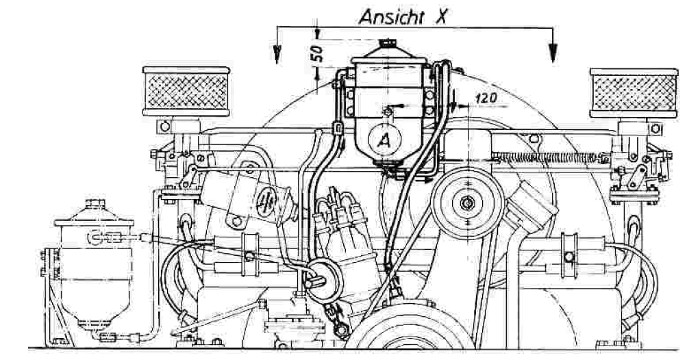
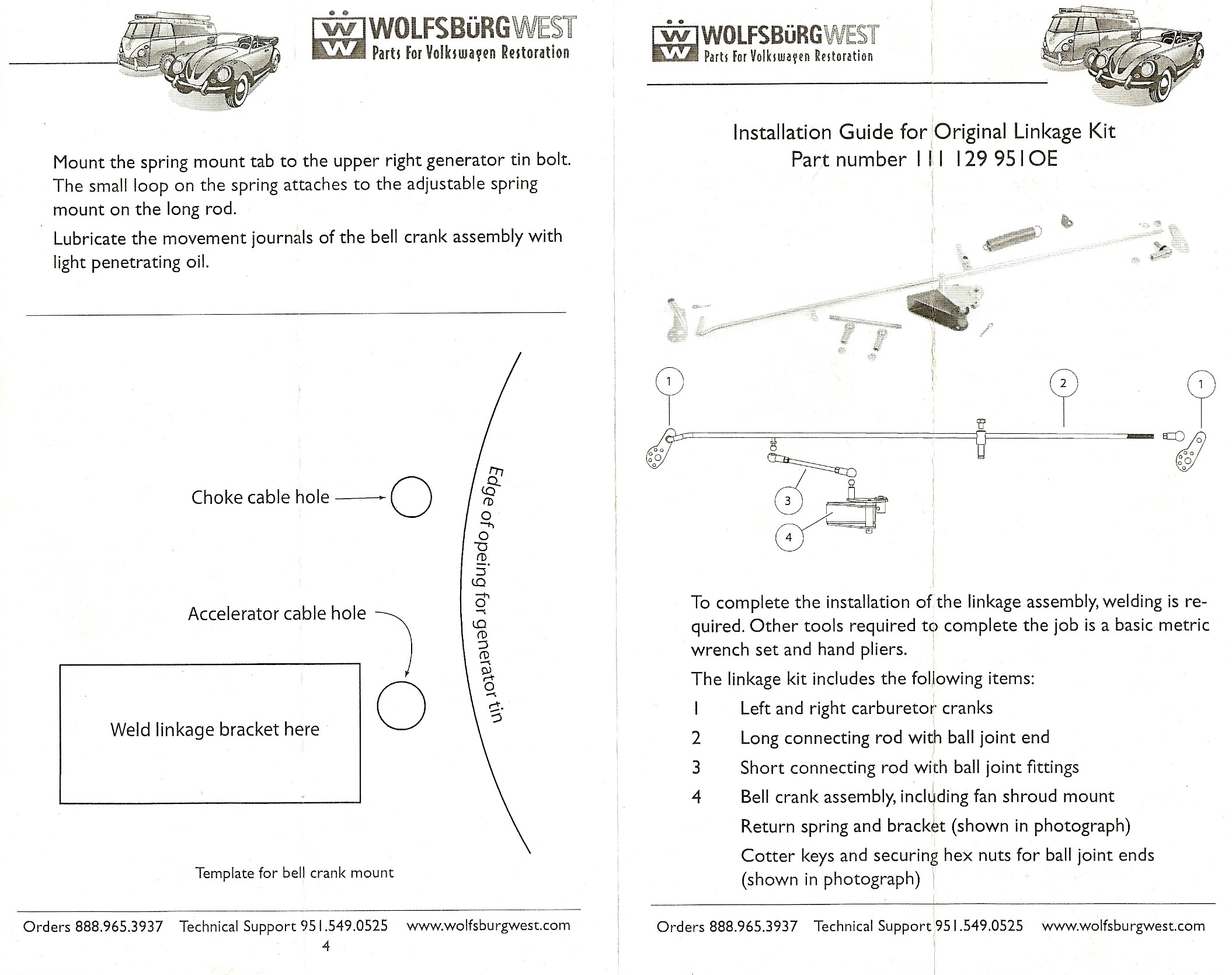
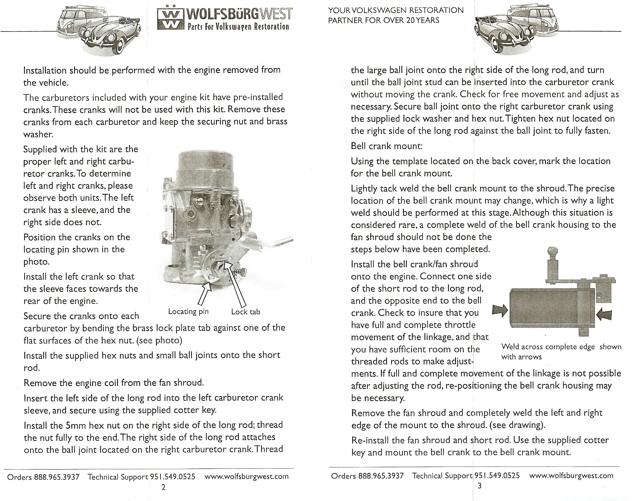
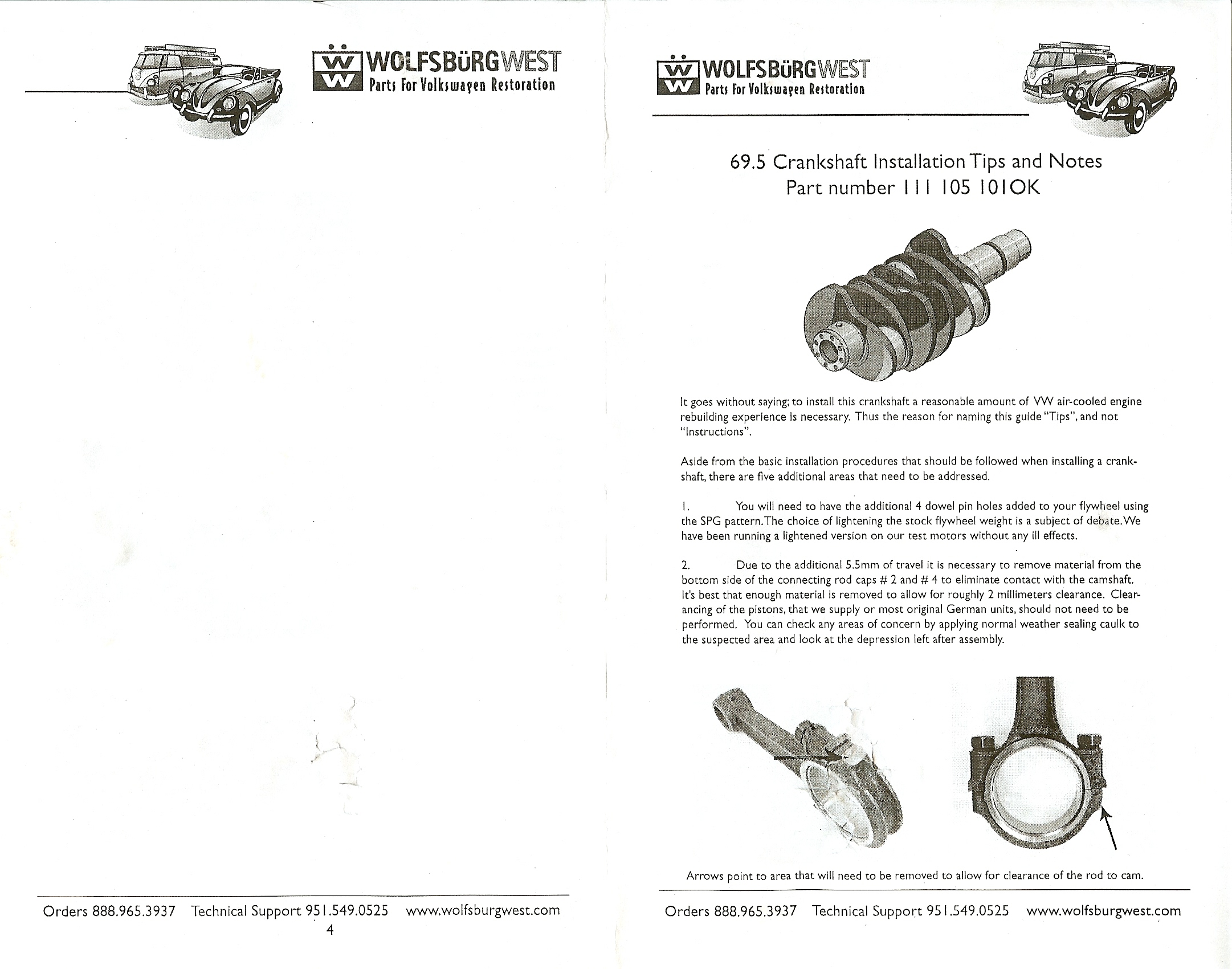
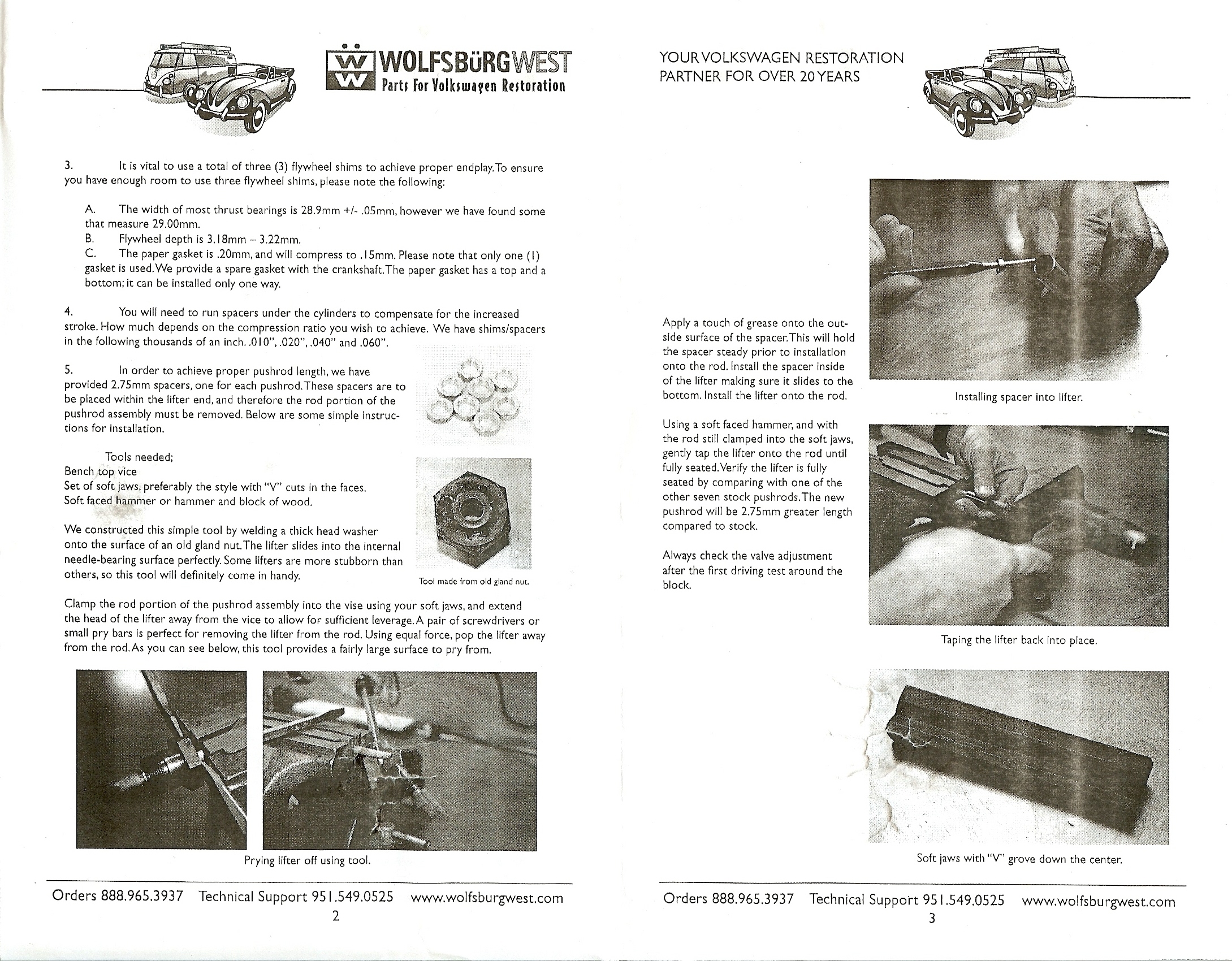
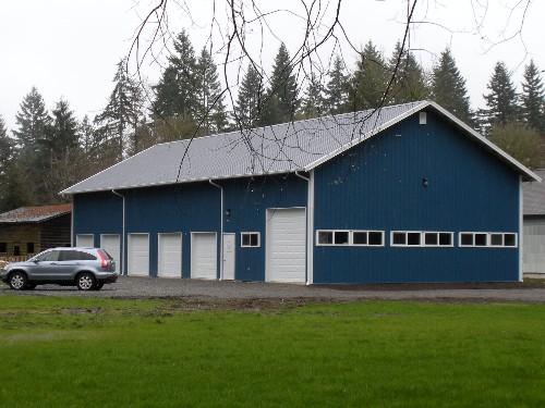