![[IMAGE]](912dream.jpg)
Darryl's 1966 Porsche 912 Project - Mechanical Repair Page
PROJECT JOURNAL ENTRIES IN CHRONOLOGICAL ORDER
Entry: 2/19/06 - Removal of the rear spring plates and torsion bars in a rusty 912 is a moment of truth. I've seen cars where the splines on the torsion bar are rusted tight and they can't be removed. If the splines on the torsion bar anchor points at the center of the car are damaged, I would be looking at a huge job of finding a good donor torsion bar tube and welding it into the body. More realistically, I would probably decide to condemn the whole project due to rust and part-out the car because of the importance of getting the rear suspension alignment perfect with my limited equipment. A little discipline in the disassembly phase makes "clocking" the torsion bars during reinstallation a piece-of-cake by making a gauge out of 1/16" thick plywood and marking the un-loaded angle of the spring plate, once it was unbolted from the rear "banana" arm. Once marked, the torsion bar came out easily from the center splined mount but was rusted tight on the spring plate's splines. Normally, that would be a really bad thing because I would have to withdraw the torsion bar through that little access hole in the quarter panel! No worries, I'm almost ready to cut the rear quarter panel section out (dashed black lines) and I can remove both the torsion bar and the spring plate as one piece and put it in my bench vise to hammer the spring plate off! The insides of the torsion bar tubes were perfect, no rust or damage to the splines that a little wire brushing could not cure.
![[IMAGE]](http://www.darrylsgarage.com/912/912LRKR2.jpg)
Entry: 10/7/06 - Today I began the installation of the restored right rear suspension. The splined torsion bar is kind of a puzzle to figure out in order to get the spring arm to align with the angle I marked on my plywood gauge when I disassembled it. I figured it out through trial-and-error but the technical manual spells it out pretty straight forward; 40 splines on the inboard end, 44 splines at the outboard end, one spline change inboard = 9 degree, one spline change outboard =8 degrees 10 minutes. All this dinking around with the torsion bar ended-up with the ride height restored to its original position on my 912 and all the freshly repainted suspension components bolted back in with new rubber bushings installed. I will be needing to have the front and rear wheels aligned once the car is all back together but the ride height is back to the "high" original factory position.
![[IMAGE]](http://www.darrylsgarage.com/912/912RRKRq.jpg)
Entry: 3/12/07 - I needed to take a break from filler and block sanding work so I decided it was time to dive into the fuel tank and determine its condition and begin the restoration process. The first step was removing the fuel level sender, which came out in pieces, add an additional $108 unplanned replacement part hit to the project budget! I figured new was the only way to go and hate to see a '6/65' dated sending unit heading for the land fill. With the fuel level sender out of the tank, I was able to peer inside with my flashlight and fiber optic scope. What I found was good news, really minimal surface rust just starting in a few spots and nothing looking like it's rotting through, the ideal application for using the old molasses rust removal technique. Last night I applied a coat of SEM Rust Seal on any rust I could see just to stabilize it until I sandblast the outside of tank. I figured removing the "sombrero" shaped tarboard spare tire base stuck to the top of the tank was the logical place to start. I broke-out the trusty old Black & Decker heat gun and putty knife and went after hardened and tightly stuck on tarboard. Well, a couple seconds with the heat gun and tar board turns into a molten blob of tar... what a mess and very slow going. Here's a shot of the fuel tank as I was just getting started.
![[IMAGE]](http://www.darrylsgarage.com/912/912fuel2.jpg)
Once I got the majority of the tar off the fuel tank, I turned to paper towels and lacquer thinner to remove the remaining. The gray paint on the tank is also lacquer so I had to be careful not to wipe too vigorously or it came off with the tar. The top side turned out looking like minimal sand blasting will be required to have it prepped for new gray paint. I looked-up the replacement tar "sombrero" part number (901.556.101.20) and saw that dC Automotive's website lists one for $18 so I placed an order and will see what shows up. Installing a new one looks like a job for the heat gun and a whole bunch of patience but there is no other way to do it right.
![[IMAGE]](http://www.darrylsgarage.com/912/912fuel3.jpg)
The bottom side of the tank had a tar and foam seal around the perimeter that needed to be removed using the heat gun and lacquer thinner technique. A little bit of cleaning with lacquer thinner revealed the center section of the bottom which is exposed to the outside of the car was actually painted gray as well and not undercoated as the accumulated road grime had lead me to believe. The bottom side is ready for sand blasting as well. Overall I am quite pleasantly surprised by the condition of the fuel tank and will save about $150 by not having to have it professionally "boiled" at a radiator shop.
![[IMAGE]](http://www.darrylsgarage.com/912/912fuel4.jpg)
The next step will be rinsing the inside of the tank with hot water to remove any rust particles and then filling it with a 5 parts water to 1 part molasses solution and let it sit for a few weeks. I've used this rust removal technique before and while it is slow and smells bad, it is environmentally safe (you dump the used solution on your grass) and really works great. After the molasses is removed from the tank I'll again rinse it well with hot water and flush it with Eastwood Company's Metal Wash to keep it from flash rusting. Once it dries thoroughly, I'll swish a couple cups of Marvel Mystery Oil inside to protect the surface from rusting until gas is introduced. Sand blasting and painting the outside will be the last step, with much care to keep the sand out of the inside of the tank. The Marvel Mystery Oil will dilute with the first tank of fuel, which will probably have more of it added to help break-in the newly rebuilt engine if things go as planned.
Entry: 3/25/07 - I wanted to get the surface rust removal process on the inside of my gas tank started today since I figured it would be about a month to 6 weeks of "brewing" required to allow my molasses solution to "consume" all the surface rust spots in the tank. I really don't think it's possible to leave it too long and I want the tank to be ready for sandblasting and painting outside once the warm dry weather gets here. The fuel tank is listed as having a 16.4 gallon capacity in the owners manual so in order to get a 5:1 ratio of molasses to water I needed about 3 gallons of molasses. It would cost a fortune to buy 3 gallons of molasses at the local grocery store so I ran to the local co-op farm & ranch feed store and picked-up a 5 gallon bucket of molasses intended for livestock for about $24 with tax. I thoroughly rinsed all the remaining gas and rust flakes out of the gas tank with scalding hot water, sealed all the openings other than the filler tube, added the 3 gallons of molasses and topped it off with cold water. Tonight it sits on end with a heater close by to warm the mixture so I can stir and slosh it around until all the molasses is dissolved into the water. I've got to say, molasses is messy stuff and the area looked like a homicide scene until I hosed it all down! Once the solution is mixed I'll find some small rusty hardware to put a wire around and hang in the molasses solution inside the filler tube to pull out periodically and inspect as an indicator of how the process is working on the areas in the tank I can't see until I drain it.
![[IMAGE]](http://www.darrylsgarage.com/912/912tank3.jpg)
Entry: 3/26/07 - Now before you go thinking I must have a very understanding wife, I should explain I'm also thankful to have a rental property across the street from my house currently undergoing a complete remodel! There was a reason I left the bathtub intact when I did the demo work... car projects! I actually replaced all the dry rotted studs behind those knocked-out tiles from outside the house... but that's another big project! So what I have here is something that looks like a crime scene out of the TV show, The Sopranos! I checked on the electric quartz heater cooking my gas tank "still" this morning and the temperature of the "molasses cocktail" was just over 100 degrees F and ready for a good stirrin'. I took a 4' piece of 3/32" brass welding rod, bent it into an 'L' at the bottom and stuck on some duct tape to form a paddle. Pop the other end into my cordless drill and ran it down the filler tube and started "whippin' it good" to make sure all the thick molasses was dissolved into the water. Looked like Denny's coffee... you could stand a spoon in it! I Put the quartz heater away and we're good to go... or forget about it now for a month!
![[IMAGE]](http://www.darrylsgarage.com/912/912tank4.jpg)
Entry: 4/10/07 - I dropped off all 4 of my brake calipers with John at Goldline Brakes of Seattle and they should be completely rebuilt with an OEM silver finish for $89.95 each in about 3 weeks. I had a bunch of questions for John, the answers; Don't use silicone DOT5 in a Porsche, use DOT4 because of the high heat (and how it draws moisture into the system) from disc brakes and bleed annually, Yes, they rebuild 911S aluminum front calipers, Yes, they rebuild 914 rear calipers, No, I don't need new crush washers on the banjo fitting on the front calipers, and several more that I can't recall at the moment. Ironically he looked at my calipers and showed me his signature parts that show these calipers had all been rebuilt by him before, back in the '90s! I walked out of his shop highly impressed and having learned several important things about brakes, such as how to correctly bleed the ABS system on my '97 VW Passat! Lots of high-end antique Ferrari brake parts laying around so I must be in the right place for Porsches!
![[IMAGE]](http://www.darrylsgarage.com/912/912brks1.jpg)
Entry: 5/9/07 - I also picked-up the rebuilt brake calipers from Goldline Brakes of Seattle and here's how they turned out. I paid extra for a brake fluid resistant, baked-on silver polymer coating with a clear coat instead of plating them and the extra cost was $45 per caliper ($180 total) bringing the total cost to rebuild all 4 calipers to like new condition to $587 with sales tax. I think the polymer coating will be much more resistant to discoloring from exposure to brake dust than a soft silver zinc plating (since nobody does silver cadmium plating anymore due to the high hazmat disposal costs) and it still looks like how they came from the factory. Suffice to say, I'm very happy with how they turned out.
![[IMAGE]](http://www.darrylsgarage.com/912/912brks2.jpg)
Entry: 9/22/07 - Progress on the 912 is stalled at the body shop. I took the doors and rear deck lid to the body shop at the beginning of August and they're still sitting there waiting for a slack period to develop, which is OK since the owner of the shop always treats me so well. With my daughter off to college and as a recent widower, I'm realizing that I'm ready for a break on the 912 and the isolation of my home shop so I took a part-time "apprenticeship" at my buddy's VW/Porsche shop (Wolfsburg Motorwerks). It's a good excuse to get out of the house a couple days a week and work on other people's projects for awhile with the benefit of getting my parts at wholesale and machining work at cost. My first project will be fixing a few problems with my 356C's engine and then doing a complete rebuild of my 912's engine this Fall. I'm loving the experience I'm getting and all I'm learning from the professional mechanics I work with. I'll be getting the 912 painted over the winter and will get back to reassembling it in due time.
![[IMAGE]](http://www.darrylsgarage.com/912/at-work2.jpg)
![[IMAGE]](http://www.darrylsgarage.com/912/at-work.jpg)
Entry: 9/29/07 - Working part-time at a shop that specializes in early air-cooled Porsche and VW cars has its perks, the best of which is getting parts at wholesale. I'm starting to acquire the parts I'm going to use to bring the original, matching serial number engine in the 912 back to life. I'm not going to spare any expense with the engine so the first parts I've purchased are the real "trophy" parts; a genuine Porsche aluminum oil cooler (retails at $636) and a set of Mahle 82.5mm (stock) bore, 9.3:1 compression ratio, Nikasil-lined aluminum cylinders and pistons (retails at over $2400), wholesale is about half price! This is going to be one sweet motor. I'm thinking a nice new Scat counter-weighted crankshaft is next on the shopping list and those retail at about $1500.
![[IMAGE]](http://www.darrylsgarage.com/912/912part1.jpg)
![[IMAGE]](http://www.darrylsgarage.com/912/912part2.jpg)
Entry: 11/26/08 - Today I picked-up my 912's freshly repainted fuel tank from Ken, my painter, at Aldercrest Auto Rebuild in Lynnwood. This is the same tank I had filled with molasses way back when to remove the rust. Prior to stripping the paint, I had taken it to Westco Auto Supply to have them perform the paint match scan and print out the mixture so Ken had a basis to work from and then he mixed up the paint to match and test against the original paint. Once Ken was done, I took the tank to a radiator shop to have it hot-tanked to make sure all the molasses was out of it, pressure tested and a couple leaks repaired. After the radiator shop, I brought the tank back home, stripped, media blasted and filled the dents and rust pits using JB Weld. I then returned the tank to Ken for painting. It sure was a lot of running around but as you can see in the following photos, The tank has come a long way from how it looked originally and it's ready to install good as new!
![[IMAGE]](http://www.darrylsgarage.com/912/912ftnk1.jpg)
![[IMAGE]](http://www.darrylsgarage.com/912/912ftnk2.jpg)
Entry: 12/7/08 - I figured the paint on the fuel tank had cured and hardened-up sufficiently to make it a bit more forgiving to bumps and scrapes. Time to finally install the fuel tank seal (Porsche part no. 901.504.932.20) by removing the adhesive backing and sticking it to the bottom of the spotweld flange. This seal is made of very high density closed-cell foam which won't absorb water or fuel and provides a good bit of cushioning for the gas tank, which would weigh about 90 pounds when full!
![[IMAGE]](http://www.darrylsgarage.com/912/912ftnk3.jpg)
What I really wanted to do was finally get this tank safely nestled into its "steel cocoon" in the front of the 912 and safely away from damage sitting in my basement! I was hoping it would look really pretty sitting there and by damn I think it does! Plumbing that tank is going require removing it one more time so no sense in bolting it in tight right now.
![[IMAGE]](http://www.darrylsgarage.com/912/912ftnk4.jpg)
Entry: 1/6/09 - Now that I've got my 912 engine on the new test stand, it's time to do a partial tear-down and evaluate its current condition. I plan on adjusting the valves and doing a compression test first and if the numbers look good, install my known to be working OK set of Solex 40 PII-4 carbs that came on my 356C (which were rebuilt by John Walker) and getting it running. A working fuel pump is critical to accomplishing that goal and I can only assume the one off my engine needs some love, especially since it looks like somebody installed machine screws with nuts to compensate for some stripped threads (on left in following picture). I happen to have what looks like a good fuel pump core (on right in the following picture) that is missing some parts but has unmolested original machine screws holding it together. I also have a Stoddards fuel pump rebuild kit (can you believe these things now cost almost $70?) on hand to install so I disassembled both pumps and they're soaking in my carburetor cleaner dip tank overnight.
![[IMAGE]](http://www.darrylsgarage.com/912/912fpmp1.jpg)
A couple things make me think this engine was recently rebuilt, at least the top-end anyway. As you can see in the following photo, the pushrod tubes still have very fresh gold annodized plating, something I didn't see on tired engines I tore down in my apprenticeship at the Porsche shop. The annodized plating tends to oxidize fairly quickly and turn to surface rust.
![[IMAGE]](http://www.darrylsgarage.com/912/912exam3.jpg)
I also opened up the oil sump plate and took a close look at the cam and lifters and as you can kind of see in the following photo, they're nice and uniformly shiny, no scoring or discoloration. This further supports my belief that this is probably a fairly fresh engine. A set of aluminum Mahle cylinders indicates that the last engine rebuilder didn't cut any corners on cheap replacement cylinders as these aluminum Mahles are the Nikasil-lined ones that cost about $1500 for the set! So I've removed all the cooling tins, cleaned debris out of the cylinder cooling fins and have the oil cooler in the parts washer to remove all the oil and dirt clogging its cooling fins. Tomorrow I'll adjust the valves and do a compression test with my fingers crossed for good numbers! Perhaps a peek inside the sparkplug holes with my fiberoptic scope wouldn't be a bad idea either.
![[IMAGE]](http://www.darrylsgarage.com/912/912exam2.jpg)
Entry: 1/12/09 - IT'S ALIVE!!! Over the last couple days I wrapped-up all the little tasks required to make sure my 912's engine had every potential for starting right up and running well on the test stand. I had to make a run to the local import auto parts store this morning for a new oil pressure sending switch to get my test "idiot light" working and a run to the Shell station for some fresh premium gas but then we were all systems GOOD-TO-GO! I primed the carbs with a couple big squirts of raw gas down the throats with an eye-dropper to get the engine to quickly turn over and prime the freshly rebuilt fuel pump and fill the carburetor bowls. The moment came, I flipped the power switch, the "idiot light" oil pressure light came on so I hit the starter trigger a couple times and, well... watch what happened...
The crappy paper gasket that comes with Mann oil filters and seals the oil filter canister leaked purple Swepco oil like crazy, dripping on the ground under the engine so I immediately shut the engine down. Since then I've replaced the pinched paper gasket with the old used rubber one that came on the oil filter canister and the leak is gone. A quick check with the timing light shows the Bosch 022 distributor I scrounged isn't advancing correctly so it will need to be sent to Ed Fall at Vintage Werks to be rebuilt and recurved. Once that issue is resolved, I'll "dial-in" those single shaft Solex 40 PII-4 carbs and attempt to get the engine to idle down correctly. I also observed a leak coming from the bellhousing, a new rear main seal will be needed as well but I was planning on having the flywheel resurfaced for a new clutch disc and pressure plate anyway so no biggie!
Entry: 1/23/09 - Over the last couple days I've been carefully tearing-down my 912's engine, what fun! I have come to realize how great of investment of my time the one year "apprenticeship" at my friend Jack Morris' Porsche repair shop has been and I owe him a debt of gratitude. I can say that I actually know what I'm doing, what to look for and where everything should be and if it's missing or wrong. It is really a great feeling of accomplishment for me to have challenged myself and dive into something I used to feel was way beyond my comfort zone... Ok, I guess I should hold off on congratulating myself until after I have this baby back together and running like a scalded cat again! Today I took my "Torque-Meister" tool down to the shop in Ballard and used Jack's brake lathe to machine a little bit off the 36 mm socket so it would work on a Porsche flywheel gland nut. The "Torque-Meister" is actually an ingenious VW tool that uses the flywheel starter ring teeth to turn a small gear that multiplies the torque by 9x. Torque spec for a flywheel gland nut is 350 foot lbs, which my "Torque-Meister" had no problem loosening in the following photo with a long breaker bar.
![[IMAGE]](http://www.darrylsgarage.com/912/912torq1.jpg)
One of the goals of my "apprenticeship" was to assemble a set of special VW and Porsche air-cooled 4-cylinder engine building tools. Here's the set I've put together based the items that I had to borrow from Jack in order to build the engines during my training.
![[IMAGE]](http://www.darrylsgarage.com/912/912tool1.jpg)
So with the flywheel off, I was able to put the "short block" engine in my engine stand and remove the pulley and "3rd piece" of the case that houses the oil pump in the front of the engine. As it sits tonight, I'm ready to split the case, disassemble the crank/pushrods and start measuring tolerances to figure out what needs to be done to this engine!
![[IMAGE]](http://www.darrylsgarage.com/912/912tdwn1.jpg)
Entry: 1/27/09 - The garage was quite a bit warmer this evening so I went ahead and split the case on the engine, removed the crankshaft and disassembled the connecting rods. The bearings look pretty well discolored and worn and the crank journals are scored indicating there are a lot of miles on this engine. A quick measurement with my digital calipers and it looks like the case and crank have never been line bored or machined, indicated by standard outside #1 bearing and journal diameters. The case doesn't look to need to be line bored but the crank will need to be machined to 1st undersize. The knock I was hearing might be #3 crankpin as it was significantly more worn than the other 3 and the clamshell bearing was more discolored. It looks like this engine had a recent top-end refresh on the original bottom end. For the original, matching serial number engine, these are actually pretty fantastic findings!
![[IMAGE]](http://www.darrylsgarage.com/912/912eng-a.jpg)
Entry: 2/8/09 - Over the last week I've completely disassembled the crankshaft and cam by removing the gears. The cam has been shipped to Elgin Cams to be reground to factory grind and the crank shipped off to the local machine shop in Tacoma that is used by all the VW/Porsche shops in the Puget Sound region to be machined "1st undersize" or -.25 mm. I will be taking the heads, connecting rods and flywheel to NW Connecting Rods to have them rebuilt and resurfaced. I can get remachined and shot-peened cam followers and rocker arms from Jack's shop supply and turn my old ones in as cores. As it sits right now, all my internal engine work is farmed out and I can concentrate on cleaning and restoring the engine sheetmetal. I did want to capture a shot of the casting marks on my engine block halves which show the May, 1965 casting date (5 dots = May and "65" is the year).
![[IMAGE]](http://www.darrylsgarage.com/912/912cast1.jpg)
Entry: 2/12/09 - Today I got a call from Jerry at NW Connecting Rods that my machining work was complete... already! I just dropped this work off on Monday! I collected the rebuilt heads and connecting rods, plus the resurfaced flywheel, all ready to put into the new engine. I stopped-by Jack's shop to get the correct roll pins used to retain the clutch pressure plate and noticed my crank hadn't gone out yet. I plan on having the crank, flywheel and clutch balanced as a unit as soon as the crank returns from the machine shop. So here's the way those dirty old parts came back from the machine shop, all pretty and shiny, kinda addicting to stare at, isn't it?
![[IMAGE]](http://www.darrylsgarage.com/912/912eng-b.jpg)
Entry: 2/18/09 - Today I finally finished the first of my engine tin pieces. My theory on VW and Porsche engine cooling tins is that the factory covered them with a thin layer of paint for a very good reason, to dissipate heat faster. I have never been a big fan of powdercoated engine tins because it just doesn't look original and it is applied so thick. I deviated from my normal high-temperature engine enamel and tried a new product this time, Eastwood's Extreme Chassis Black Satin because I have been having chipping issues with the regular engine enamel. Over the last several days, I've degreased, straightened and media blasted the left heater box then gave it 3 thin coats of the Eastwood's paint from different angles, each coat left to dry 24 hours apart. I think it has exactly the right amount of gloss compared to original engine tins. The following photograph compares the completed left heater box with the unrestored one from the right side of the engine.
![[IMAGE]](http://www.darrylsgarage.com/912/912tins1.jpg)
Today I also picked-up my re-ground camshaft from the shop that had been sent into Elgin Cams to be reground to 912 / Super 90 spec. Rather than do a core swap, I requested my original be returned to me so there are absolutely no issues with clearance in my case since there are no cam bearings on these engines. Doesn't Elgin do a nice job refurbishing these cams, it looks brand new! Now all I am waiting for is my crankshaft to return from the machine shop in Tacoma, Jack said it's down there with 3 other ones from the shop so it should be back any day. Once I get the crankshaft back, I'll do all the measurements and order up the correct bearing sets before sending the crank, flywheel and clutch assembly off for balancing at Action Auto's machine shop in Shoreline.
![[IMAGE]](http://www.darrylsgarage.com/912/912cam1.jpg)
Entry: 2/20/09 - Today I wanted to run my old cam followers and lifters down to the shop and turn them in to Jack as cores for a set of already reconditioned ones. During the course of disassembling the rocker assemblies, I wanted to document the condition of them. As you can see in the following photo, the points where the rocker arms meet the valve stems are extremely worn and galled. As part of the reconditioning process, the machine shop welds new material into the worn areas, grinds them to spec and then they are heat treated to harden them.
![[IMAGE]](http://www.darrylsgarage.com/912/912eng-c.jpg)
I think I finally found the definitive reason for my engine suddenly developing a knock when I was running it on the engine test stand, the cup at the end of the adjusting screw on cylinder #1 exhaust valve is broken off, allowing the push rod to escape or at least caused some slop. This would have allowed the cam to "hammer" on the cam follower and that's what it sounded like to me. Perhaps 6 years of sitting with the valve open caused metal fatigue? Jerry at NW Connecting Rods said the valve springs were toast and this tappet cup breaking would be consistent with that type of problem. Perhaps a top-end tear down and refurbish is mandatory for any Super-90 engine that's sat for more than a few years?
![[IMAGE]](http://www.darrylsgarage.com/912/912eng-d.jpg)
Entry: 3/11/09 - I took a little trip to Manzanillo, Mexico last week and while I was gone, my crankshaft returned from the machine shop after receiving a 1st-under grind and polish. Jack happened to have all the necessary bearings on the shelf so I didn't have to order any. Now the crankshaft, flywheel and clutch pressure plate are off at Action Auto's machine shop in Shoreline for balancing. Meanwhile, there's some really sketchy business happening in my kitchen, I've scrubbed the case pieces with ABC Corrosion Buster and placed them in my dishwasher for a spa treatment! I can begin assembling the bottom end of the engine as soon as Action Auto finishes with the balancing.
![[IMAGE]](http://www.darrylsgarage.com/912/912eng-e.jpg)
Entry: 3/23/09 - The crankshaft, flywheel and clutch came back from Action Auto's machine shop in Shoreline and show the signs of having been balanced. Rotational balancing only differs from wheel balancing in the act of removing weight from the heavy side instead of adding weight to the light side. Lightening is achieved in removing material from the clutch pressure plate by drilling into it and then marking where the unit is "clocked" upon assembly. Guess it might be worth the trouble of marking any clutch I remove from now on.
![[IMAGE]](http://www.darrylsgarage.com/912/912ebld0.jpg)
So now it's time to put the big puzzle back together. All the new or newly-machined pieces are back from the machine shop. Three exceptions that don't delay the start of the "bottom-end assembly" are the rocker arms being reconditioned, a new flywheel gland nut and an S-90 engine "top-end" gasket kit. So now I'm wrapping up with the cleaning and inventory of the case hardware and miscellaneous bits prior to putting the "bottom-end" together... this is starting to get fun!
![[IMAGE]](http://www.darrylsgarage.com/912/912ebld1.jpg)
One little gem I found while working in my "apprenticeship" was the availability of these sweet little bottom-end gasket kits from Wrightwood Racing, where they add on the premium-quality "Viton" (a space-age synthetic rubber made by DuPont) seals to a high-quality Reinz kit. I sure would like to build a "drip-free" engine and this is one small bit of insurance that might just happen.
![[IMAGE]](http://www.darrylsgarage.com/912/912ebld2.jpg)
Entry: 3/25/09 - We got down to brass-tacks today. Time to convert that table full of metal into the whole reason for having a sportscar, a high performance engine! I've been going over notes and reviewing the Secrets of the Inner Circle... the Maestro's writing makes me drift back to those hippy-dippy days, I remember the '70s! Fast-forward to the present; my crank is all assembled, drive gears and connecting rods and I'm feeling good about bearing tangs being clocked downward and bolts torqued to 32.5 ft. lbs. on oiled threads.
![[IMAGE]](http://www.darrylsgarage.com/912/912ebld3.jpg)
I also reassembled the cam and timing gear, which was a bit challenging considering how brittle camshafts are. I torqued the bolts to 18 ft. lbs. using the stock retainers and then carefully drove the retaining pins back through the flange at the base of the cam. The Porsche gods were smiling today, no new parts reduced to scrap and two completed subassemblies!
![[IMAGE]](http://www.darrylsgarage.com/912/912ebld4.jpg)
Entry: 3/26/09 - The bottom-end of the engine is assembled! I installed the bearings, crank and cam into the case dry and bolted the two halves together, making sure the crank didn't bind while slowly bringing the bolts up to 29 ft. lbs. torque. I found that everything spins easily, dry, so I disassembled everything, installed the cam followers, pre-lubed all the contact points on the crank and cam, put DIRKO sealant on the halves and bolted it all together. Tonight it sits, ready for the third piece of the case to be installed to cover the timing gears! Woo-hoo, everything is progressing very nicely and without any additional drama and yes, I did remember to install the cam plug!
![[IMAGE]](http://www.darrylsgarage.com/912/912ebld5.jpg)
Entry: 4/1/09 - Tonight I finally got some time to work on the engine. I started with installing the flywheel, using the existing end-play shim, old gland nut and old "soft iron" gasket that goes over the dowel pins at the end of the crank. End-play measured at about .003" and the spec is between .005" to .007" so I need a thinner shim so there's more play.
![[IMAGE]](http://www.darrylsgarage.com/912/912ebld8.jpg)
I turned the engine on its end so it was sitting on a couple 2x4s to support the flywheel off the bench so I could install the "3rd piece" of the case that covers the timing gears. I made sure all the rubber tubes and O-rings were in the right places, applied a thin coat of DIRKO on both side of the paper gasket and bolted it all together at 14.5 ft. lbs. torque, including the special bolts that support the rear engine carrier. I installed the oil pump gears and cover, the engine tin that goes behind the pulley and then used the P 73 special tool rear seal installer (see photo below), installed the woodruff key, rear pulley and bolt.
![[IMAGE]](http://www.darrylsgarage.com/912/912ebld7.jpg)
So here it sits, ready to haul down to the shop in Ballard and swap flywheel shims until I find one that fits perfectly. Once I have the right shim, I can install the new "soft iron" gasket, new flywheel seal and new gland nut before torquing it to 350 ft. lbs. I can't wait to start installing the cylinders, pistons and heads, that should go fast!
![[IMAGE]](http://www.darrylsgarage.com/912/912ebld6.jpg)
Entry: 4/9/09 - I finally got time to haul the assembled bottom-end down to the shop in Ballard to resolve the shim issues to get .005" of end-play and did the final assembly of the flywheel this evening. As you can see in the photo below, I used my factory tool, P 212 Oil Seal Arbor to install the premium flywheel seal made of "Viton" and it went into place without any damage.
![[IMAGE]](http://www.darrylsgarage.com/912/912ebld9.jpg)
I installed the new "soft iron" gasket, lubed the polished seal contact flange of the flywheel with Wurth assembly silicone, installed the new gland nut with a drop of red LocTite and torqued it to 39 ft. lbs. using the "Torque-Meister" which multiplied the force 9 X to give 350 ft. lbs. of torque at the gland nut. Once the gland nut was installed, I lubed the roller bearings inside it with Bosch distributor grease so it is ready for installation. Tonight it sits in the engine stand, ready to install the pistons, cylinders and heads.
![[IMAGE]](http://www.darrylsgarage.com/912/912eblda.jpg)
Entry: 4/13/09 - Assembling the top-end of the engine was today's project. Everything pretty much went by-the-book with no wrist-pin clips lost inside the engine or somewhere in the shop. I felt very calm and relaxed, made sure all the rings were clocked correctly and the wrist-pin clips were seated and secure. This job would be nearly impossible without the factory Hazet 83 mm ring compression tool and with it the job is a breeze.
![[IMAGE]](http://www.darrylsgarage.com/912/912ebldd.jpg)
![[IMAGE]](http://www.darrylsgarage.com/912/912eblde.jpg)
The cylinder cooling tins were installed on the bottom side of the cylinders and held in place against the new pushrod tubes with wire springs. The headspace looked perfect so the heads went on and were progressively torqued from 15, 20 and 23 foot lbs, both sides at the same time so the case wasn't stressed. Everything turns freely so the next step is assembling the valve train, which is waiting on the rocker arms to come back from the machine shop.
![[IMAGE]](http://www.darrylsgarage.com/912/912ebldf.jpg)
![[IMAGE]](http://www.darrylsgarage.com/912/912ebldb.jpg)
Earlier today I made a trip down to Auburn to pick-up my brand new exhaust system I had dropped-off at Performance Coatings where I had them blasted and covered with a satin gray ceramic coating that will withstand extremely high temperatures and keep them from rusting. I plan on painting the heater boxes black but letting the "J-tubes" stay the satin gray.
![[IMAGE]](http://www.darrylsgarage.com/912/912ebldc.jpg)
Entry: 4/20/09 - My rebuilt rocker arms came back from the machine shop last Thursday but Jack didn't like how they looked and sent them back for further finishing. So while I'm stalled on my engine assembly, what better time than now to rebuild the pedal cluster! My pedal cluster was a rusty mess and in an attempt to disassemble it, I broke the clutch pivot shaft!!! Luckily I had the pedal cluster out of the '68 front clip and was able to cut a usable clutch pivot shaft out of it... literally cut since it had the same issues with being rusted tight. After a lot of work to get a complete set of usable parts, I blasted, painted and assembled the pedal cluster using new poly-bronze Weltmeister bushings and it works perfectly tonight! I also got a bunch of engine tins blasted and painted so the delay on the rocker arms really isn't keeping me from moving forward, yet!
![[IMAGE]](http://www.darrylsgarage.com/912/912foot1.jpg)
Entry: 4/22/09 - Today the rocker arms arrived and with the replacement "valve adjusting screw" (a.k.a. the cup shaped part I found was broken upon tear-down) I bought from Stoddards with a new adjusting nut, I'm ready to complete the top-end assembly of the engine! The machine shop in Tacoma did a marvelous job of welding new steel to the worn and galled tips that contact the valve stem and then ground them to size, polished and heat-treated them for $5 per piece, $40 total. So, all the farmed-out pieces have finally returned to the nest!
![[IMAGE]](http://www.darrylsgarage.com/912/912ebldh.jpg)
While I've been waiting for the rocker arms to return, I've been getting all the external engine pieces required to complete the assembly and perform the break-in run ready to go. All the engine cooling tins, heater boxes and generator mounting parts required to actually run the engine on the test stand have been media blasted and painted using Eastwood's Extreme Chassis Black Satin and are ready to install. I also used the official "oil filter canister silver" paint sold by Stoddards to repaint the oil filter canister after media blasting the outside of it. I still need to deal with the cooling fan, which I will media blast and probably paint cadmium silver. I like how the heater boxes look painted black against the 'J-tubes' in the satin gray ceramic exhaust coating
![[IMAGE]](http://www.darrylsgarage.com/912/912ebldg.jpg)
Entry: 4/24/09 - I thought all the pieces had returned to the nest but one key piece is still missing. The oil temperature sending unit which is off with my dash instruments, being cleaned and recalibrated at North Hollywood Speedometer. With the rocker arms finally back from the machine shop, I could assemble the valve trains on both heads, the photo below is just one side's valve train, exploded style:
![[IMAGE]](http://www.darrylsgarage.com/912/912ebldk.jpg)
The valve trains were assembled with ample priming of the push rod tubes with Swepco 30W oil squirted through a piece of vacuum tube pushed over the tip of my pump oil can and with all new wavy spring lock washers. Once the valve covers were snapped into place with the retaining bales, it was time to turn my attention to installing the new OEM Porsche aluminum oil cooler that is so much more efficient than the original steel ones. These oil coolers are pretty spendy but with such a huge benefit in a cooler-running engine, I couldn't resist the little secret upgrade hidden under the stock doghouse shroud.
![[IMAGE]](http://www.darrylsgarage.com/912/912ebldi.jpg)
Finally it was time to mount the heater boxes and start with the cylinder tins. I need to make a little modification to my new engine stand as it interferes with the sheetmetal lip at the back of the #3 cylinder tin. I will continue with the intake manifolds while blasting and painting the cooling fan next. A new Bosch generator needs to be liberated from the parts stash too. Oh boy, things are starting to move quickly now!
![[IMAGE]](http://www.darrylsgarage.com/912/912ebldj.jpg)
Entry: 4/26/09 - Assembly of the new (rebuilt) generator using all the original fan and pulley parts was the first task on the list today. I had already media blasted and painted all the parts yesterday so everything was good and cured before putting them together. A new fiber spacer between the fan base and the doghouse shroud really sets-off the the fresh black paint and new generator.
![[IMAGE]](http://www.darrylsgarage.com/912/912ebldn.jpg)
Mounting the heater box / J-tube exhaust pipes was the next task on the list and they went into place with very little coaxing. The freshly restored cooling fan / hub assembly looks great, too bad nobody will be able to see it once the engine is in the car!
![[IMAGE]](http://www.darrylsgarage.com/912/912ebldm.jpg)
Installing the heat shield that spans the gap between the heat flapper boxes and protects the oil pump from the heat radiating from the muffler was the last task for the evening. The heat shield is a new item purchased from Stoddards and needed about 1/4" trimmed off using tin-snips to fit perfectly. I thought I should wait until I was fresh to install the muffler since it's so ackward and prone to scratching if one isn't extremely careful. I also plan on using Wurth exhaust assembly paste to make sure the union between the J-pipes and muffler are totally sealed and that probably would benefit from better visibility of daylight to accomplish.
![[IMAGE]](http://www.darrylsgarage.com/912/912ebldl.jpg)
Entry: 4/28/09 - Today I attached the muffler and oil filler can on the engine. After thinking about it, I removed the J-tubes / heater boxes on both sides and installed the muffler first. It took a couple good whacks with a deadblow hammer to get all the flanges on the muffler to line up with the ports on the heads but once attached it gave a good solid point to insert a hammer handle into the pipes where the J-tubes insert and give them a bit of an adjustment too. When all was adjusted, the J-tubes slid in easily so I could apply Wurth exhaust assembly paste and get a perfect seal. Jack fixed me up with some special exhaust flange nuts he has specially manufactured for Wolfsburg Motorwerks to allow for getting a small wrench on the nut on the bottom sides of #1 and #3 cylinder... a trade secret so I can't say more! On the oil filler can, I made sure to paint the inside of it with high-temperature black engine paint to seal it from moisture to prevent rust and trap any possible blasting media that might be stuck in the cracks from media blasting the rust out of the inside. Blasting the inside of the canister is not recommended by all the books but I figured between rinsing it with carburetor cleaner, blowing out with compressed air and then painting it, there wasn't much chance any blasting media would be left inside.
![[IMAGE]](http://www.darrylsgarage.com/912/912ebldo.jpg)
Entry: 4/29/09 - Today my task list began with adjusting the valves so once the engine was clocked back to TDC, I could insert the distributor drive shaft. Inserting that skinny washer down into that big, open timing gear cover, before the distributor drive shaft is inserted always makes me a bit gripped-up! Luckily I have a VW factory special tool that makes it really easy, especially after a little practice before actually inserting the washer. Once the distributor was installed and the rotor clocked right where #1 cylinder tick mark is supposed to be, everything else went quickly; fuel pump, oil lines, oil filter canister and coil. The only thing missing is the oil temperature sender and unfortunately I momentarily forgot that when priming the oil filter canister, I over-filled it with Swepco 30W oil and it started running out the empty sensor hole! That explains why the engine is tilted-over in this photograph, oil can't run uphill! I'm going to have to scrounge and borrow an oil temperature sender from the shop until North Hollywood Speedometer gets mine back with the gauges they're refurbishing for me. You can also see the Bosch blue coil I've "backdated" with paint in the photo, the only evidence is covered by the coil wire boot.
![[IMAGE]](http://www.darrylsgarage.com/912/912ebldp.jpg)
Entry: 4/30/09 - Today I was able to borrow an oil temperature sender and temporarily install it on my engine to stop the oil from draining from the oil filter canister that I over-filled when I primed it. It just so happened that North Hollywood Speedometer called this morning to inform me that my gauge rebuild would be more extensive than originally thought because my oil temperature gauge itself needs to have it's "guts" replaced to work with a new sender and the speedometer "guts" need replacement too. Total cost will be nearly $900 for all 5 gauges and they are sending the new oil temperature sender now so I can install it on the engine before running it the first time. Tonight I also installed the spark plug wires with the rubber wire holding plugs and O-rings to hold the wires in place. The new breather hose from the oil filler can to the right head, the carburetors and throttle linkages were also installed. The fancy Knect wire air cleaners are just for "track use" and the snorkle cans with paper filters will be run on the street.
![[IMAGE]](http://www.darrylsgarage.com/912/912ebldq.jpg)
Entry: 5/5/09 - The last remaining pieces on the engine came together today. First of all the layered chrome / clear powdercoated valve covers came back from Seattle Powder Coat and look like fresh plating! After one final valve adjustment re-check, gaskets were glued-in using Durko and the valve covers were snapped into place using Wurth assembly silicone to lube the bale and prevent it from scratching the powdercoating. A bottle of Crane Cams Break-In Super Lube was poured in the crankcase with 4 quarts of 30W Swepco synthetic oil, the stuff with zinc to keep the cam from going flat.
![[IMAGE]](http://www.darrylsgarage.com/912/912ebldr.jpg)
I'm still waiting on a new Solex style fuel line and just reinstalled the old one that is held together with hose clamps so I can do the initial 20-minute break-in run at 2000 RPM to seat all the new parts. I've got everything ready to mount the engine on the test stand and begin running it. The perfect stopping point to take care of some family business for a few days.
![[IMAGE]](http://www.darrylsgarage.com/912/912eblds.jpg)
Entry: 5/29/09 - Figuring out how to set and hold the throttle open at 2000 RPM required fabricating a bracket. My solution spanned existing mounting holes cast in the VW bus bellhousing with a piece of angle iron so that I could attach a spare gas pedal linkage (with the ball at the end) to the bellcrank and use a vise-grip to clamp the throttle rod in position.
![[IMAGE]](http://www.darrylsgarage.com/912/912ebldt.jpg)
Once all the pieces were in place, it was time to finally give my freshly rebuilt 912 engine its first start-up and 20-minute break-in run. This video captures the experience, wouldn't you know the particular vise-grip I had chosen to hold the throttle rod would have to pop open when I needed it most and required two hands to put it back together, luckily I had another one handy.
Entry: 6/9/09 - I returned from a trip to Colorado to extract my 81-y-o mom from the ICU and get her back on the mend. What should I find waiting inside the door? My instruments returned from North Hollywood Speedometer while I was away! Nothing like admiring the work of craftsmen in the spring sunshine of home sweet home.
![[IMAGE]](http://www.darrylsgarage.com/912/912nhs1.jpg)
Entry: 6/22/09 - Finishing up the dirty work of blasting and painting the remaining engine tins was one more task standing between getting the car on the road this summer and me. I also had some major cracks that required MIG welding and finishing work to repair on the rear tray where the supports that bolt to the muffler are attached. After many hours of work, almost all the remaining piece have been media blasted and painted using Eastwood's Extreme Chassis Black Satin and are ready to install.
![[IMAGE]](http://www.darrylsgarage.com/912/912ebldu.jpg)
Installation went pretty smoothly other than I wish I would have put the outer pulley cover on before the muffler because it required removing one of the rear motor mounts to get it on! Getting all the tailpipe clamps installed was also part of this job. As you can see in the following photo, just the carburetor pre-heat flaps and linkages need to be blasted and painted and the engine is ready to install in the car!
![[IMAGE]](http://www.darrylsgarage.com/912/912ebldv.jpg)
Entry: 6/29/09 - Once again eBay came through with the pieces I needed to keep making progress on the project. I had failed to recognize the tranny mount currently on the car is a later, 912 only "square block" style that was introduced April, 1966 on 5-speed transmissions starting at #229361. I needed to find one of the earlier types that was also used on the 911's 905 tranny. Luckily a quick search on eBay turned one up at a buy-it-now price of $45 plus shipping. If you watched the YouTube video, you might have noticed the starter motor on my engine test stand was straining to turn over the freshly-rebuilt motor with all-new parts. I figured one of those fancy high-torque starters I read about on the various BBS websites would be a good solution. I found one on eBay that uses a modern Japanese style starter motor with a HP rating of 2.0hp and 525 foot lbs. of torque. I got it for $104, buy-it-now price without a core charge, which was a steal. The carbs are off at 356 Carburetor Rescue for a complete remanufacture so not long now before I roll the car back on to the 4-post lift and install the engine!
![[IMAGE]](http://www.darrylsgarage.com/912/912ebay4.jpg)
Entry: 7/9/09 - Today's task was degreasing the transaxle plus media blasting and painting the engine and transaxle mounts. Once again, my favorite purple biodegradable cleaner and wire brush made quick work of the caked-on grease and dirt on the transaxle. The engine and transaxle mounts are hanging in the paint booth drying and should be ready to go after curing a couple days. Not many more things need to be media blasted before I roll the car back onto the 4-post lift and start installing the brakes and such! I also installed the new high-torque starter on the engine test stand and it spins the engine nice and fast so that problem is solved, now I'm just waiting for the carbs to return from 356 Carburetor Rescue to make another test run on the stand to dial-in the carbs and get the engine ready for installation in the car.
![[IMAGE]](http://www.darrylsgarage.com/912/912tran1.jpg)
Entry: 7/12/09 - So here the engine sits with all the mounting hardware and carburetor pre-heat pieces added, it just needs the carbs back from 356 Carburetor Rescue and a Solex-style fuel line from the fuel pump to the carbs. The transaxle is also ready to go into the car, save a set of throttle bellcrank bushings. Transaxle work included; clutch throw-out bearing and all replacable wear-point bushings are new, the early/911 style transmission mount is attached with new correctly-sized M8-1.25 x 31 mm studs, a new Bosch starter and a new grounding strap. I also began work on the wooden steering wheel by chemically stripping the old varnish finish. I'm kind of excited to do something so far out of the normal restoration work for a change of pace. I believe it is time to roll the 912 body back onto the 4-post lift and start with installing the brake and fuel systems!
![[IMAGE]](http://www.darrylsgarage.com/912/912ebldw.jpg)
Entry: 7/20/09 - Restoring the old, original Solex-style fuel line required getting 3 new hose fittings "swedged" onto new 6 mm German woven fuel hose.
![[IMAGE]](http://www.darrylsgarage.com/912/912hose1.jpg)
I found a hose and fitting place locally that performed the task using aluminum fittings and the total cost was $4.93 with tax, I provided the new fuel hose. I'll need to figure out how I'm going to get the only remaining one at the fuel pump attached, once I've mounted the new carburetors on the engine. All I know is that there is nothing left to complete once the carbs return from 356 Carburetor Rescue any day now!
![[IMAGE]](http://www.darrylsgarage.com/912/912hose2.jpg)
Entry: 8/3/09 - The time has come to make patterns for the engine compartment sound-proofing pads and transfer them to the closed-cell neoprene foam from McMaster-Carr. I ordered a 1/2" thick by 42" x 72" pad to make the engine compartment sound-proofing way back in March of 2007. I believe closed-cell is the ticket, you can spray adhesive on it and press it into place without the glue soaking into it and distorting the surface like open cell foam will do. According to the specifications on the McMaster-Carr website, this particular foam is rated to withstand temperatures to 210 degrees F, is self-extinguishing when a flame source is removed and withstands oil and gasoline exposure without breaking down. Sounds like the perfect stuff for lining an engine compartment to me! Closed-cell foam also doesn't absorb water (or any liquid) so it won't trap moisture that causes rust. The 1/2" thick by 42" x 72" pads cost roughly $90 and are listed as "Neoprene/EDPM/SBR Foam Rubber" on the website. I have the patterns transferred to the foam and ready to run down to Steve Shepp's upholstery shop tomorrow to use his fancy Bosch foam saw. The Bosch foam saw works like an electric kitchen knife, making a perfectly crisp 90 degree edge not possible with a razor blade or scissor. Making the patterns using heavy, grocery bag weight craft paper took hours but the results should look perfectly tailored once installed.
![[IMAGE]](http://www.darrylsgarage.com/912/912foam2.jpg)
Entry: 8/4/09 - Today I ran the 1/2" thick by 42" x 72" roll of closed-cell neoprene foam with the outlines of the engine compartment sound-proofing pad down to Steve Shepp's shop in Ballard to use his $600 Bosch foam saw to cut them out. About 15 minutes later the completed pads were loaded back in my car and the job was done. Ahhhh, the joy of using the right tool for the job! Now to do the final fitting and cementing them into place on my 912.
![[IMAGE]](http://www.darrylsgarage.com/912/912foam3.jpg)
Entry: 8/5/09 - Final fitting of my custom-tailored 1/2" thick closed-cell neoprene sound-deadening engine compartment padding was the final step this morning before gluing them into place. The product I chose for the job was Wurth Hi-Temp Spray Adhesive specifically formulated for high temperature applications like foam car headliners so it's perfect for a hot engine compartment. I also used standard plumbing pipe insulation foam as the tubes to connect the rear window defrosters to the heater channels, held with standard wire ties. The factory used foam tubing as a "muffler" to deaden the engine noise that the carburetor pre-heater tubes transmit to the passenger cabin. So the engine compartment is all ready for mounting the engine, time to start working on the brakes!
![[IMAGE]](http://www.darrylsgarage.com/912/912foam4.jpg)
Entry: 8/9/09 - Preparing the new and old brake parts for reassembly is progressing well. The new rear brake rotor hubs are always painted an industrial gray on Porsches so mine is no exception. I removed the hand brake lever from the cabin and have it disassembled for blasting and painting gloss black. A few more details to complete before installing the rear calipers I had rebuilt by Goldline Brakes here in Seattle way back in April, 2007.
![[IMAGE]](http://www.darrylsgarage.com/912/912brks3.jpg)
Entry: 8/10/09 - As of 11:35 PM this evening, The rear brakes are completely reassembled! I was able to blast and repaint the parking brake handle and reassemble it, reinstall the parking brake cables, rear brake rotor hubs, backing plates, rebuilt calipers, brake pads, brake lines, rear shocks and wheel spacers and am now heading to the hot tub with a cold beer! Next I can start on the front brakes and pedal cluster! One more huge step towards getting this car on the road while the weather is still nice enough to drive it!
![[IMAGE]](http://www.darrylsgarage.com/912/912brks4.jpg)
Entry: 8/15/09 - I got a good start on the front brakes this afternoon, beginning with removing the hubs and mounts and cleaning up the front shocks. I just put a new pair of Bilstein shocks on the back to replace the low-budget KYB gas ones that came on the car and since the front ones show no signs of leaking and don't "bounce" when I push down on the front bumper, I think they're still good and don't need to be replaced. I decided to paint them yellow to match the new rear ones and will leave them alone for now. I'll do some further detailing on the tie rods and begin plumbing the new brake lines next. The hubs of the new front rotors will also need to be painted gray just like the rear ones before I start putting everything back together with the rebuilt calipers and new pads.
![[IMAGE]](http://www.darrylsgarage.com/912/912brks5.jpg)
Entry: 8/20/09 - While I was out on a 3-day cruise of the San Juan Islands, a package arrived containing a trophy part scored on eBay for a mere $20. The eBay gods were smiling on me when I bid on the elusive, first year of production only windshield washer fluid reservoir used on my 912. While it might look ugly and rust-stained to a casual observer, it's a precious jewel to a car geek like me! I have seen these things go for around $100 on eBay and can't believe I was the only bidder and got it at the reserve price! This doesn't help with my eBay addiction but I do keep the discipline of making only one bid and not getting caught up in the emotion of the auction.
![[IMAGE]](http://www.darrylsgarage.com/912/912wpr3.jpg)
The early windshield washer reservoir was one of those ideas that didn't last long in the real world. First of all, and indicated by the rust on the one I found, somebody got the great idea of stashing it in a body cavity up near the cowl that wasn't treated with any kind of rust preventative, just bare steel. As you can see in the photo I scanned out of my owners manual, it's really in an awkward position to fill and so spilled washer fluid went onto the German square-weave carpet and soaked into the rubberized horse hair pad under it. One detail the owners manual photo is missing is there is a piece of German square-weave carpet that is glued to the side of the trunk compartment, hiding the fender bolts. The old one in my car has a circle cut with cloth binding tape sewn around the inside to allow the neck of the windshield washer reservoir to poke through. I will have to work with Steve Shepp to duplicate this feature on my new trunk carpeting. I also got a call from 356 Carburetor Rescue that my Solex carbs are done and will be mailed to me in about a week!
![[IMAGE]](http://www.darrylsgarage.com/912/912wpr4.jpg)
Entry: 8/23/09 - Cleaning, blasting and painting of all the parts comprising the front disc brake hubs and caliper mounts continued over the weekend. I'm searching for all the new copper crush washers used on the "banjo-fittings" that connect the master cylinder and front calipers to the new brake lines. I've got an order from Pelican Parts coming in with 2 new front inner wheel bearing seals that is due Wednesday and I hope to have all the pieces ready to assemble the front brakes by then. I'd love to have the brake system completely assembled, filled with fresh DOT 4 fluid and bled, ready to go by the time the rebuilt carbs get here and I can turn my attention to a final test run of the engine on the test stand and dial-in the new carbs. Things are really starting to come together now!
![[IMAGE]](http://www.darrylsgarage.com/912/912brks6.jpg)
Entry: 8/25/09 - My order from Pelican Parts arrived yesterday so there was nothing to stop me from finishing brake system reassembly. As of this afternoon, the front brakes and master cylinder are completely assembled, ready for the introduction of DOT 4 brake fluid and bleeding the air out of the lines. The master cylinder fluid reservoir is installed in the "smugglers box" and the pedal cluster is installed in the passenger cabin. No worries about being ready to focus on installing the rebuilt carburetors on the engine and dialing them in on the test stand when they arrive by the end of the week! Here's a photo of the right side brake rotor and caliper:
![[IMAGE]](http://www.darrylsgarage.com/912/912brks7.jpg)
Here's a photo of the left side and you can see the new master cylinder tucked up next to the rack-and-pinion steering.
![[IMAGE]](http://www.darrylsgarage.com/912/912brks8.jpg)
Entry: 8/26/09 - Oh man, I am so psyched, my remanufactured Solex 40 PII-4 carburetors arrived from 356 Carburetor Rescue in todays mail and they're everything I dreamed they would be. Silver cadmium plating as was found on my early 912 but these are late '69 carbs with the fully evolved secondary circuit ports that alleviated the flat spots in the RPM curve found on earlier versions. These '69 carbs required "back-dating" to remove the split shafts and vacuum ports. New chrome-moly solid shafts with new bushings, machined throats to fit new brass butterflies and the correct jetting for sea-level plus flow bench testing and the float levels set. Everybody who has used these guys say there's nothing more to do but follow the installation instructions posted on their website. Of course I had a set of the original factory part number tags I've been hoarding in my parts stash to add to the carburetors, "616.108.103.04" for the left one and "616.108.104.04" for the right one. The remanufacture cost using my core carburetors was $1399 plus shipping. Definitely not cheap but the headaches I'm saving by having these all dialed-in and tested for me is well worth the extra $500 I would have saved by having a machine shop do the repairs and leaving me with the jetting, float level setting and testing issues to resolve. I think the investment I made in the engine is worth not risking a burnt valve because of a carburetor problem I'm not equipped to discover. I now have the exact original factory engine configuration, working as new for my 912!
![[IMAGE]](http://www.darrylsgarage.com/912/912carb1.jpg)
![[IMAGE]](http://www.darrylsgarage.com/912/912carb2.jpg)
Entry: 8/27/09 - See that brake pedal? It's hard! Today I poured DOT 4 brake fluid into the master cylinder reservoir and then attached my trusty EZ-Bleeder which uses 20 PSI air pressure (from a spare tire or air tank) to push brake fluid into the system. All I need to do is open and close the bleeder screws on the calipers, starting with the furthest one from the master cylinder, the right rear. One secret to the EZ-Bleeder on a Porsche is to use a stick to hold the brake pedal down slightly so the valve stays open in the master cylinder and allows the brake fluid to flow through it. So now I can concentrate on mounting my new carbs and dialing them in on the engine while it's still on the test stand. First task is re-checking the valve adjustments after the 20-minute test run.
![[IMAGE]](http://www.darrylsgarage.com/912/912brks9.jpg)
Entry: 8/29/09 - So the moment of truth arrives... after re-checking the valve adjustments post break-in run and finding only minor variations and setting them back to spec, I bolted the new carburetors on. Next I installed the new fuel line with the "swedged" hose fittings with new banjo-bolt seals. It was time to hook-up fuel and power and start the engine on the engine stand with the new carburetors on. This time I used an outboard motor type priming bulb on the fuel line which worked great and I'm considering installing one on the car! The engine was a little "cold blooded" but eventually fired-up and without the normal high-pitched "squawking" and popping fuel back through the throats I encountered during the break-in run. The new carburetors are EXCELLENT! The engine purrs at idle with none of the erratic behavior I normally see with Solex carburetors! It took minimal adjustments to bring the idle down to 800 and achieve even synchrometer readings of "7" all the way around! The money spent on remanufacturing these carburetors seems to be very well spent, I can't wait to see how it pulls through the RPM curve with them when I drive the car... SOON!!!
![[IMAGE]](http://www.darrylsgarage.com/912/912carb3.jpg)
Entry: 9/1/09 - Over the last couple days I've been quickly making progress towards putting the engine back into the car. The first thing I had to solve was a fuel leak from both my newly remanufactured carburetors. Both carbs leaked profusely, actually dripping gasoline onto the engine tins next to the intake manifolds when they sat overnight. I was able to isolate the leaks on both sides to the "non-return ball valve" at the bottom of each bowl under the accelerator pump, the single brass fitting with a ball bearing inside and little filtering screen on them. I noticed that each non-return ball valve had a copper compression sealing washer on them and I attempted to tighten them slightly but they still leaked. Luckily I have a couple Royze brand Solex P40II-4 carburetor rebuilt kits from Stoddards on hand and replaced the copper compression washers with the fiber type found in the Royze kit. With the fiber type washers, the leaks immediately stopped and my carburetors are now bone dry. The following photograph shows the two sealing washers side by side, exactly the same size but different material. I let the folks at 356 Carburetor Rescue know their sealing washers were failing via e-mail so hopefully nobody else will encounter this problem.
![[IMAGE]](http://www.darrylsgarage.com/912/912carb4.jpg)
Everything is ready for reinstallation of the engine and transmission at the backend of the car. The clutch cable, shifting rod with all new bushings, speedometer cable and throttle rod are back in place with new rubber bellows or sealing grommets As you can see in the following photo, everything is cleaned and ready to go.
![[IMAGE]](http://www.darrylsgarage.com/912/912ctrl2.jpg)
Inside the cockpit, the shifting and pedal controls are all installed and buttoned-up with the floorboards installed. I will have to make the final adjustments in pedal travel and shifter movement once the engine is installed. Of course I went to install the clutch cable yesterday and couldn't find the clevis fork and retaining pin so I ordered new ones from Pelican Parts last night. First thing this morning, I found the Ziploc baggie labeled, "Clutch Fork" right in the box I searched through several times yesterday. I really can't believe I'm this mentally feeble, I swear there must be Gremlins toying with me in my garage!
![[IMAGE]](http://www.darrylsgarage.com/912/912ctrl1.jpg)
The real fun began with the installation of the gauges I had rebuilt for me by North Hollywood Speedometer, installed with new rubber sealing rings from Stoddards. Everything went well except I need to find a set of metal mounting clamps for the clock. These are the 'L' shaped brackets that hold the gauge in using the knurled nuts and threaded shafts on the instrument case. I'm not sure if the clock didn't have them or I've misplaced them but I'm currently missing the pair and need to find some. I bought a set of nice servicable 912 seats on eBay and should be getting them by the time the car is ready for test driving since I don't want to put any pressure on Steve Shepp to get mine reupholstered while he's still doing chemo. Next step is getting all the electrical components hooked-up and finishing the dash trim and steering wheel.
![[IMAGE]](http://www.darrylsgarage.com/912/912dashk.jpg)
Entry: 9/3/09 - Today's objective was to have all the tasks remaining before installing the engine completed. So the engine came off the engine stand which required removing the car from the 4-post lift and using the lift to support the engine as I unbolted it from the stand. So I look at the engine sitting on the moving dolly on the ground and realize there's something missing from the new heater boxes I bought from Dansk, THE HEATER CABLE GUIDE TUBES!!!
![[IMAGE]](http://www.darrylsgarage.com/912/912htrb1.jpg)
So I took a look at the old ones and make a few measurements, yep 5/16" O.D. tubing. I go to NAPA and buy some 5/16" OD weldable steel brake line tubing. Cut the tubing to size based on the original. Blast the tubing in the blasting cabinet so any plating that would inhibit a good weld is removed.
![[IMAGE]](http://www.darrylsgarage.com/912/912htrb2.jpg)
I used my Dremel tool to grind a channel at the seam joining the front and rear of the new heater box, carefully measured from the old one. I also used the Dremel to expose some clean steel on the heater box on which to lay some MIG welds. The brake line was extremely thin so I had to "dial down" the MIG amps and wire speed so it wouldn't burn through. A little creative use of wood blocks and a dandy German-made clamp and everything is ready to weld. I then repeated the same steps for the other side, wire brushed all the burned paint and gave it a fresh coat of high-temperature black paint to cover my repairs and the missing cable tubes were no longer missing!
![[IMAGE]](http://www.darrylsgarage.com/912/912htrb3.jpg)
Installing the clutch and pressure plate, making sure to clock the red marks where the machine shop had balanced them was the next step. I used special 8.8 grade allen-head cap screws torqued to 25 foot pounds and proceeded to join the engine and transaxle.
![[IMAGE]](http://www.darrylsgarage.com/912/912htrb4.jpg)
So as of this evening, everything is good-to-go on mounting the engine/transaxle unit back into the car. I need to figure out how I'm going to use the 4-post lift to lower the car onto the engine and save myself as much heavy lifting as possible. Suffice to say, I am one extremely stoked individual! An update on a couple items; I heard back from Jim Kaufmann at 356 Carburetor Rescue within hours of my e-mail about the leaking copper washers and he appreciated the feedback, also I found the clock 'L' brackets I had put in a "special" place so I wouldn't lose them!
![[IMAGE]](http://www.darrylsgarage.com/912/912ebldx.jpg)
Entry: 9/9/09 - Today was the moment of truth, installing the new Motorcraft group 51R 12-volt battery using the new ground cable that arrived from NLA Parts just yesterday. Nothing started smoking when I hooked up the cables, that was a good sign. The group 51R battery is the same one used in the 90's Mazda Miata and it fits nicely inside the original battery's footprint using all the original securing hardware.
![[IMAGE]](http://www.darrylsgarage.com/912/912elec4.jpg)
First thing I tested was the headlight switch, brake lights, wiper switch, on down the list. The only problems were switched turn signal indicator bulbs in the tachometer, non-working emergency flashers, non-working dome lights, bad ground in the ambient temperature gauge light and reversed connections on the brake/running light bulb in the left tail light.
![[IMAGE]](http://www.darrylsgarage.com/912/912elec2.jpg)
Everything else worked perfectly, especially the tough stuff like wipers, brake lights, parking brake "on" indicator, clock, starter switch and the various "idiot" lights. As of tonight only the dome lights and emergency flashers need further investigation and that's not critical to test driving the car. Like clockwork, the special 1.5 thread pitch M12 x 80 mm bolts needed for the early 911 style tranny mount arrived from McMaster-Carr today so tomorrow the engine can go in! With normal M12 bolts carried at my hardware store coarse thread pitch is 1.25 and fine is 1.75 so I though it was fortunate McMaster-Carr carried them since the ones used for the later tranny mounts were 95 mm long and wouldn't work in the early mount. Don't the new headlights and front turn signals look absolutely gorgeous with the lights on in the dark?
![[IMAGE]](http://www.darrylsgarage.com/912/912elec3.jpg)
Entry: 9/10/09 - The big day is finally here, the project milestone of reinstalling the engine and transmission! Having a 4-post lift makes this job extremely easy, no grunting or floor jack balancing, just slowly lowering the body onto the engine. First step is lifting the engine high enough to get the motor mounts a minimum of 30" off the floor and the transmission mounts 20" off the floor to mate up with the height of the attaching plates in the body. I used the same technique as I used on my WWII jeep's engine and tranny, beams and chains. 3/8" eye bolts attached to the engine and tranny mounting points provided a good place to hook up the chains.
![[IMAGE]](http://www.darrylsgarage.com/912/912dtin1.jpg)
Once again I called upon my favorite props in my mechanical dramas, milk crates and moving dollies. I wanted a slight upward tilt to the shifting rod coming out of the end of the transmission so I could feed it through the hole at the end of the tunnel and mate it with the shift coupler so a 4 x 4 wood block provided it. Mookie, my miniature Schnauzer looks a little nervous sitting under the lift but no worries Mookie, it's solid as a rock! Once the weight was lowered onto the milk crate / moving dolly stand, the chains and beams were removed and the engine/tranny carefully and slowly maneuvered into place.
![[IMAGE]](http://www.darrylsgarage.com/912/912dtin2.jpg)
Lowering the lift with the car onto the engine/tranny was just a matter of lowering a few inches, checking clearances and pushing the whole unit forward once the shifting rod was lined-up with the hole in the back of the tunnel. The whole operation was extremely straight forward and required very little physical effort, just patience.
![[IMAGE]](http://www.darrylsgarage.com/912/912dtin3.jpg)
So, once the four 12 mm bolts were secured in the tranny mounts first and then the motor mounts, the weight could be lifted off the rolling platform and it could be dismantled. Hooking up the wires and cables didn't take long and all that remains to be done on the bottom side is installing the CV joints and heater tubes.
![[IMAGE]](http://www.darrylsgarage.com/912/912dtin4.jpg)
Hooking up the wires, fuel lines and big carburetor pre-heater tube was all that was required on the top side. Polarizing the generator is all that remains on the top side before it's ready to start the engine. I'm extremely excited to button everything up and take this car out for a test drive while the weather is still warm and dry!
![[IMAGE]](http://www.darrylsgarage.com/912/912dtin5.jpg)
Entry: 9/11/09 - Today started with a trip down to Ballard to visit Wolfsburg Motorwerks for supplies for my next step in the project, disassembly, cleaning, inspection and reassembly of the CV joints prior to installing the rear axles. I also stopped by Steve Shepp's upholstery shop to show him the "engine in" photos and visit. Once home it was time to mount the new Vredestein HR165x15 radials on the 4-1/2" painted steel wheels I've had stashed away for a couple years. I still eventually want 4-1/2" chrome wheels but the painted ones will do for now. Just for fun I printed off a copy of the original window sticker, it should get some comments when the car is at the upholstery shop for the gray German square-weave carpet installation and bodyshop for the cut-and-polish of the paint.
![[IMAGE]](http://www.darrylsgarage.com/912/912whl1.jpg)
![[IMAGE]](http://www.darrylsgarage.com/912/912whl3.jpg)
![[IMAGE]](http://www.darrylsgarage.com/912/912whl2.jpg)
Entry: 9/14/09 - This session's tasks started with a fun little side project, mounting new hubcaps. NLA Limited offers rechromed disc brake style hubcaps without holes for early 356C and 904 cars without center crests. I have lots of nice original center crests on badly scratched and dented hub caps so I ordered the plain ones and drilled my own holes for my crests and saved some cash. I think the new hub caps on the painted 4-1/2" steel wheels look quite stunning. I've also finished installing the heater hoses, polarizing the generator, final clutch adjustment and a bunch of other small tasks. Now the ugly task of servicing the old CV joints loomed as today's big objective.
![[IMAGE]](http://www.darrylsgarage.com/912/912whl4.jpg)
Cleaning and inspecting constant velocity joints is an extremely dirty job due to the large quantity of thick, dirty molybdenum grease they are packed full of. After hours of work, tonight both the axle shafts are disassembled and cleaned and much to my dismay, one important part is missing from one of the axles, the thrust washer! I know it wasn't on the axle when I disassembled it so now I'm going to have to run one down from one of my sources here in Seattle... CRAP! I would never in a million years reassemble this without all the correct parts installed but somebody else did! Otherwise the ball bearings and cage/housings show little wear or heat discoloration and the original "901" parts number prefixed rubber boots are still perfect and will be reused.
![[IMAGE]](http://www.darrylsgarage.com/912/912cvax1.jpg)
The "temporary" seats I found on eBay also arrived today and look extremely servicable. A little ZEP foaming vinyl cleaner and some Wurth Rubber Care on one of the cushions shows how nicely they're going to clean up. These seats should work very nicely so that Steve Shepp can concentrate on fabricating and installing the carpet and side panels first and the seats last.
![[IMAGE]](http://www.darrylsgarage.com/912/912tmp1.jpg)
![[IMAGE]](http://www.darrylsgarage.com/912/912tmp2.jpg)
Entry: 9/15/09 - An amazing thing happened last night in regards to my missing CV joint thrust washer problem. I posted my dilemma on the 912bbs.org website and a fellow 912 enthusiast named Peter Graham in Black Mountain, North Carolina responded. Peter sent me the missing thrust washer and 24 brand new Schnoor spring washers and the package will be here Thursday by 3 PM according to the USPS tracking number he provided... I live in a great world! So the CV joints are on hold until Thursday so I moved on to installing the fuel tank that I had restored over a year ago using a new fuel gauge sending unit. Everything went together beautifully and now I need to replicate the tar paper "hat" that goes under the spare tire.
![[IMAGE]](http://www.darrylsgarage.com/912/912ftnk5.jpg)
![[IMAGE]](http://www.darrylsgarage.com/912/912ftnk6.jpg)
The interior is all ready for the test drive with the installation of the rear view mirror, the "temporary" seats and the "temporary" smaller 914 steering wheel. I decided why risk somebody accidently damaging my beautiful wood steering wheel while the car is at the upholstery shop and body shop and went back with the 914 one I used before. The 912 "puck" type horn button fits perfectly and makes it look finished. I'm also really pleased with the how nicely the "temporary" seats look all cleaned-up and detailed with Wurth Rubber Care. The rear view mirror is a repro sold by Stoddards and it looks indistinguishable from the original except the mirror is unblemished.
![[IMAGE]](http://www.darrylsgarage.com/912/912seat3.jpg)
![[IMAGE]](http://www.darrylsgarage.com/912/912seat4.jpg)
The beautiful NOS SWF windshield wipers were the last thing I installed today and I'm really pleased with how nice they look against the new windshield and dash pad. Things are really getting exciting now as the final items on the "test drive checklist" are getting crossed off! 5 gallons of premium unleaded in the fuel tank, checking for leaks and firing up the engine are next on the list!
![[IMAGE]](http://www.darrylsgarage.com/912/912wind3.jpg)
Entry: 9/16/09 - I never fail to be amazed at the generosity and kindness of guys I meet through the Internet. Two days ago I thought my rear axle CV joint refurbishment was going to result in a long delay because of a part that was left out by a previous mechanic (I use that term loosely) and I made an appeal for help on the 912bbs. Peter Graham from Black Mountain, North Carolina responded quickly and not only sent me the missing part but 24 brand-new Schnoor washers at an out-of-the-pocket expense of nearly $18 to Express Mail them to me overnight! Here I sit, less than 48 hours since I discovered the missing part and I'm holding a replacement in my hands! Thanks for the return address Peter, your out-of-pocket expenses will be repaid and your heroic efforts to help me get my 912 back on the road before September is over will be rewarded!
![[IMAGE]](http://www.darrylsgarage.com/912/912cvax2.jpg)
Entry: 9/17/09 - All systems are "GO" for test drive! Today I put 10 gallons of premium unleaded in the fuel tank and found no leakage after installing an outboard motor type priming bulb in the engine compartment and "pressurizing" the system. The transaxle was filled with Swepco 201 80/90 weight gear oil and it is all ready to go. The big, nasty job was reassembling the CV joints using Swepco "MOLY" grease which was time consuming and messy but everything went together great, especially having all the new Schnoor washers that Peter Graham had sent me yesterday. Wouldn't you know that an invoice from my vintage car insurance arrived in today's mail with a proof-of-insurance document for this car so there truly isn't anything left to do except start the thing up and start driving it and dialing everything in! The bottom view of the car in today's photo shows everything is finished down there.
![[IMAGE]](http://www.darrylsgarage.com/912/912done4.jpg)
Here's the page from the October 1965 print date owner's manual for my car. It looks like I've got everything back to exactly the way it was when the car was new!
![[IMAGE]](http://www.darrylsgarage.com/912/912ownr1.jpg)
Entry: 9/19/09 - I discovered one more little problem as I ran down the "pre-test drive list" of things to check. I was able to start the engine in the car for the first time and the generator charged fine, and tachometer and temperature gauge worked fine. The problem was the gas pedal goes almost all the way to the floor before the engine RPMs respond. I took a look at the linkages, tightened every one until there were no more threads available and as you can see in the following photo there's still about �" of play in the loop in the rod at the bellcrank! I can't get the engine to rev above 3000 RPM from the driver's seat!
![[IMAGE]](http://www.darrylsgarage.com/912/912tlnk1.jpg)
I think the problem lies in the strange looking link (called the "intermediate piece" in the parts catalog) that doesn't appear to be standard and is not adjustable. I remembered the car came with Weber carbs on it and the carburetor linkages on the engine required complete readjusting to work with the Solex carbs so I'm thinking this piece was a kludge to make the Webers work. I'll have to fabricate something that allows for adjustment or buy the original parts. I'll come up with something that works temporarily so I can test drive the car if the weather cooperates tomorrow.
![[IMAGE]](http://www.darrylsgarage.com/912/912tlnk2.jpg)
Entry: 9/20/09 - I did a little research on the throttle linkage problem using the search function on the 912bbs.org and found this nugget of information. It seems the best way to take out slack is lengthening the vertical linkage behind the fan shroud, not shortening it. I was able to readjust all the linkages to take up the extra slack in the "bale" (the 'U'-shaped wire) that connects the transmission bellcrank to the one behind the fan shroud. Now I can get full throttle from the gas pedal and peg it with the pedal stop so no extra stress was placed on the throttle levers on the carbs. This is not intuitively obvious stuff to me and took some reading ( 356B/C Technical Manual page SF 25, and page SF 26) to figure out the odd geometry of those linkages. So once I got the throttle adjustments all made it was time to finally take the car out for its first test drive... of course a video was required so come along as a "virtual passenger" for the adventure! My daughter and her friend just happened to come home from college for a visit just as I was exiting the driveway! A little more carburetor linkage adjusting and centering the steering wheel is all that needs to be done before the next outing.
Here she sits, back from the first drive, the "virtual passenger" sitting in the back seat! Now I need to talk to Nick at Aldercrest Auto Rebuild about that cut-and-polish work to give that Bahama Yellow some real depth!
![[IMAGE]](http://www.darrylsgarage.com/912/912drv1.jpg)
Entry: 9/24/09 - I had a weak moment today. I had been planning on waiting to install the silver chrome P_O_R_S_C_H_E and 9_1_2 script on the engine lid until after the paint was given the final cut-and-polish. Then I figured if I used some temporary, modern, disposable speednuts, why not put them on now and remove them when the car goes into the bodyshop? What the heck, let's enjoy how nice and finished it looks now when I'm driving it around showing it off to my friends!
![[IMAGE]](http://www.darrylsgarage.com/912/912embl1.jpg)
While I was at it, I figured, let's do the hood crest as well! Oh boy isn't that pretty! I puttered around on the interior, adding new stainless steel machine screws I buffed to a chrome-like shine using jeweler's rouge to the rear quarter window and interior mirror to replace the rusty chrome originals. It was such a beautiful fall day that I couldn't help but roll the car out into the sunshine and tinker on it.
![[IMAGE]](http://www.darrylsgarage.com/912/912embl2.jpg)
Entry: 9/29/09 - After taking a 26 mile round-trip down to Wolfsburg Motorwerks in Ballard and giving the boys a chance to do a close inspection of my work yesterday, I've got a couple little problems to work out. The oil leak coming from the 'O' ring seal at the fuel pump base seems to be back (CRAP! I've got to pull that damn fuel pump out again!) and the right-side carb spits and pops at 3000 RPM. I'm in a holding pattern waiting for the throttle linkage coupler on backorder from Stoddards. I need that piece before I can really set the carbs up correctly because the linkage geometry is all wrong and it keeps the idle from dropping down when the engine gets hot. In the meantime I've replicated the tar paper "hat" that protects the fuel tank from the spare tire. I used some adhesive-backed soundproofing mat that looks similar to the original material. The original was one piece, mine is two, with tucks strategically placed so they're not visible through the cooling slots in the spare tire. I think it gets the job done pretty well and it looks original with the spare tire in place.
![[IMAGE]](http://www.darrylsgarage.com/912/912hat1.jpg)
![[IMAGE]](http://www.darrylsgarage.com/912/912hat2.jpg)
Entry: 10/5/09 - It's completing all the little details that take so much time to figure out that separate the "show and shine" car from the "concours" restoration. Electrical problems figure into that "time-eating" scheme precisely. Over the last week I've tracked down why my horn didn't honk and the dome lights didn't come on. For some reason that seems brilliant now, I stripped the wiring harness and electrical relays from that '68 front clip I bought 4 years ago to steal the steel from to fix my crumpled right corner. Like the extra pedal cluster, little did I know that the horn relay and possibly the 4-way emergency flasher relays would prove invaluable! The horn works perfectly now after swapping the relay and the dome lights and dash board light come on when the doors open! Next I need to start digging into the 4-way emergency flashers! Meanwhile I'm still waiting on throttle linkage coupler from Stoddards and have the Mann & Hummel snorkel can air cleaners blasted, painted and just about ready to install.
![[IMAGE]](http://www.darrylsgarage.com/912/912dome1.gif)
Entry: 10/6/09 - So it's finally time to mount the correct Mann & Hummel air cleaners for this mid-'65 built 912! The can/snorkel portion of the unit was blasted to bare metal to allow for removing dents and rust. The base unit that bolts to the carburetors was merely touched-up to preserve the original nomenclature label silkscreened to each side telling the maintenance person the filter element number is C 1369. A 7/65 manufacturing code is clearly visible on the left can at the base of the snorkel near the spot-welded seam.
![[IMAGE]](http://www.darrylsgarage.com/912/912eng-h.jpg)
So here's how they look mounted on the engine... pretty much a "total eclipse of the air cleaners" is what it looks like.
![[IMAGE]](http://www.darrylsgarage.com/912/912eng-f.jpg)
Comparing my engine photo to the "III/65" print date owners manual appropriate to my car shows how the stock configuration should look. Other than the "European heat" tube coming out of the front of the doghouse shroud, they're practically identical! While I had the air cleaners off, I did one more synchronization of the carbs, which I hadn't done since the last valve adjustment. Number 1 cylinder was the spitting popper, let's see if I got it cured!
![[IMAGE]](http://www.darrylsgarage.com/912/912eng-g.jpg)
Entry: 2/12/10 - Addressing the problem with the throttle linkage geometry due to a "rigged" piece between the tunnel rod and transmission bellcrank was another task on the list I crossed off today. I ordered the correct pieces from Stoddards a few months back, replacing the old parts with the factory designed vibration dampener, a new rubber bellows and the other pieces seen in the following photo. Everything is installed and the linkages are adjusted to the specifications listed in the factory manual ( 356B/C Technical Manual page SF 25, and page SF 26). This should iron out any issues with linkages binding and the resulting high idle.
![[IMAGE]](http://www.darrylsgarage.com/912/912lnkg1.jpg)
Another task on the list to be crossed off is addressing the carburetor fine-tuning to cure the engine "stumbling" between 3000 and 3500 RPM due to fuel starvation. One of the benefits of having my carburetors remanufactured by 356 Carburetor Rescue is having Jim Kaufmann's technical support. I had the carburetors jetted to the stock settings at sealevel as the baseline when they were remanufactured and they only have this one "stumbling" problem once all synced and adjusted. I described my "stumbling" problem to Jim and wondered if increasing the main jets from "155" to "157.5" would be appropriate. Jim pointed out that RPM I mentioned is the transition between idle jets and mains, so the idle jets may be starving out before the mains kick in. Then he offered to trade me my "55" idle (a.k.a. pilot) jets for "57.5" which arrived in today's mail and are ready to swap! This is over 6 months after the sale, excellent customer service Jim! Now I'm ready for some warm dry weather to give the carbs the final "dial-in" with fingers crossed that I've finally got everything perfect.
![[IMAGE]](http://www.darrylsgarage.com/912/912jets1.jpg)
Entry: 2/25/10 - So I finally got around to swapping the pilot jets today and when I removed one of the old ones, I saw it's stamped 57.5 so replacing it with the same size jets isn't going to solve anything! I sent another e-mail to Jim Kaufmann at 356 Carburetor Rescue to see if increasing the main jet size to 127.5 with jets I already have would be a logical next step. I'm interested to see what he suggests. Meanwhile, I've got an oil leak at my fuel pump to resolve. This is one of those tasks that having the car on a lift makes so easy. Once the sheetmetal plate is removed from under the fuel pump, the 13 mm nut on the bottom side can be reached with a long extension on a socket from below the car, between the heater box and muffler. I noticed a large amount of oil between the fiber insulating spacer, indicating that the O-ring around the base of the fuel pump isn't getting the job done. I put some Durko sealant on both sides of the fiber insulating spacer before reassembly to attempt to finally solve this leak. I had purchased the proper O-ring for the shaft of the fuel pump but can't see any evidence that this is the cause of the leak and won't disassemble the fuel pump unless this attempt to fix the leak fails.
![[IMAGE]](http://www.darrylsgarage.com/912/912fpmp2.jpg)
Entry: 4/13/10 - The clicking I was hearing from the front end when moving the steering wheel side to side ended up being a worn tie rod end on the outboard right side. I ordered a new one from Pelican Parts and installed it today. I removed the entire right tie rod and carefully measured the length before removing the old tie rod end so I could install the new tie rod end and adjust it to exactly the same length prior to reinstallation in the car and not mess up the wheel alignment. Now all the tasks on the list prior to the trip to Steve Shepp's shop are complete although I still need to resolve the carburetor jetting issues eventually.
![[IMAGE]](http://www.darrylsgarage.com/912/912trod1.jpg)
Entry: 5/4/10 - Now I'm getting serious about tuning this engine! I sent the Bosch 022 distributor off to trusty Ed Fall at Vintage Werks over in Utah to have it rebuilt and the advance curve verified as perfectly stock. As usual, Ed sends me back a distributor that looks like brand-new, with completely replated parts and a print-out of the actual advance curve from his fancy Sun distributor machine. Now the distributor will be a "known quantity" and eliminated from the list of possible causes for the stumbling at 3000-3500 RPM. I know it's the carburetor jetting that's causing the current stumbling but better to rule out any future distributor malfunctions now for a mere $200 with shipping.
![[IMAGE]](http://www.darrylsgarage.com/912/912dist1.jpg)
Entry: 5/7/10 - I finally bit the bullet and solved the oil leak coming from the fuel pump by spending $380 and buying a brand-new, German-made Pierburg brand (same as OEM) fuel pump. I pulled out the old one and cleaned off all the Durko sealant used in my failed attempt to stop the leak... what a mess. While on the 4-post lift, I installed the rebuilt Bosch 022 distributor, adjusted the valves (@ 100 miles) and inspected / cleaned the main jets on the right side Solex. The test drive was taking the car up to Aldercrest Auto Rebuild where the car was painted and showing Nick Stack (the owner) how the car looks all together and discuss the cut-and-polish step to be scheduled in the next week or so. The good news; zero oil leaks, the bad news; the right carburetor still has that stumbling at 3000-3500 RPM but now I know it's not the valves, main jets or distributor causing the problem.
![[IMAGE]](http://www.darrylsgarage.com/912/912fpmp3.jpg)
Entry: 8/25/12 - Ok, after 2 years of battling the spitting and popping of the "antique" Solex 40 PII carbs vs. modern fuel, my friend and expert Porsche tuner, Jack Morris finally got tired of hearing my bitching and convinced me that Weber 40 IDF carbs would completely fix all my issues and I would be a "believer" once he correctly jetted and set the float levels for me. He also showed me that Weber offers a kit that uses intake manifold adapters that allow any modifications to be simply "bolt on" and I could easily go back to using the original Solex carbs anytime I wanted to convert them back. I'd had enough headaches with the Solex problems and said, "What the heck" so he ordered a conversion kit and the proper jets.
![[IMAGE]](http://www.darrylsgarage.com/912/912wbr8.jpg)
I respect Jack's request that the proper jetting is a "trade secret" since he's put in the hours and hours of experimentation required to get the results he promises. Installing the Webers was fun, the only major difference is removing the "hard" metal fuel lines and using a "T" to run standard "Made in Germany" braided fuel lines to the back side of each carb. Jack changed the fuel line connections on the Webers from pointing backwards to pointing forwards so the fuel lines stay well away from the throttle linkages. Installed the Webers look very neat and sanitary. Because of the thickness of the aluminum Weber adapter blocks, I deleted the "phenolic" insulating spacer between the Solex manifold and Weber adapter, used to dissipate heat, thinking the additional material in the adapter plate should accomplish the same thing, also to keep the Webers lower and oil breather tube as close to the original angle as possible.
![[IMAGE]](http://www.darrylsgarage.com/912/912wbr1.jpg)
It was my desire to retain the '65 only Mann & Hummel canister air filters so I ordered a set of Weber to Solex air filter adapter plates from Mainely by Design. Carefully removing the brass air filter studs from the Webers, using the "double nut" technique and installing the adapter plates using the countersunk hex head screws went without drama (because I covered the carb intakes with masking tape so nothing would fall inside them!).
![[IMAGE]](http://www.darrylsgarage.com/912/912wbr2.jpg)
The Weber carbs require a slight modification to the factory air cleaners to allow the center jets to clear. I attached the adapter plate to the bottom of the factory air cleaners and marked the holes with a silver marking pen. A few minutes of Dremel tool grinding and the metal under the silver cresents was gone! I had a spare set of the Mann & Hummel "cans" set aside from my collection pieced together to find a perfect set and I didn't want to modify the pair of "bases" on the car with the Solex carbs. I'll clean up the "bases" I modified for the Webers with a fresh coat of paint once I establish everything works OK with them.
![[IMAGE]](http://www.darrylsgarage.com/912/912wbr3.jpg)
I also discovered the factory air cleaner bolts are about 5 mm too long so I ordered a pack of M6 1.0 x 90 mm bolts from McMaster-Carr (http://www.mcmaster-carr.com) so that the bolts don't come into contact with the top of the Webers when fully tightened.
![[IMAGE]](http://www.darrylsgarage.com/912/912wbr4.jpg)
As it sits, the front and rear air cleaner bolts don't touch the Webers so I was able to attach them firmly to test clearances until the correct bolts arrive. Everything installed, you wouldn't even suspect that there are Webers under there! I also need to fabricate a rubber gasket to seal between the Mainely by Design adapter plate and the Mann & Hummel "base" to insure a tight seal. 1/32" thick rubber sheet gasket material was also ordered from McMaster-Carr so that will also have to wait until the order arrives. For now, it's just dial in those Webers and get this 912 purring!
![[IMAGE]](http://www.darrylsgarage.com/912/912wbr5.jpg)
Entry: 8/27/12 - Jack stopped by yesterday with Sara and JB to teach me the finer points of tuning and balancing the Webers. There had been a little residual popping and spitting on #1 cylinder as I had experienced with the Solexes and with his vast experience, Jack immediatly discovered the plug gap on its plug was ever so slightly too tight such that it fouled and wouldn't spark consistently. I swore I had gapped them correctly but probably bent the electrode in the process of putting it into the hole... DOOH!!! The old "ASSUME" makes and "ASS" out of "U" and "ME" strikes again! The Solex carbs probably wouldn't pop & spit anymore but now that I've driven the car with the Webers, I wouldn't go back based on performance but for originality, which is still always an option if the desire for a "concours" car arises again but I'm kind of over that and really just want to enjoy driving the car. When driving the car with the new Webers, I noticed sometimes they "bucked" when accelerating, like I was pushing the gas pedal down too fast. Jack said he puts an additional spring on the Webers he installs in customer's cars to add resistance during acceleration and slow the rotation speed ever so slightly so the squirt of fuel from the accelerator pump doesn't get ahead of the rush of air from the opening butterflies and create a stumbling effect as the mixture ratio self corrects. My exotic mixture of adapter plates and Mann & Hummel filters creates a little more difficult problem in mounting an additional spring compared to the usual hooking to a notch in the bottom of K & R filter bases. So I pondered my options overnight and had an "epiphany" today when looking at the Zenith 30 NDIX carbs in my 356C, the springs and brackets might work perfectly and I have a "boneyard" of parts so I scrounged up a set and went to work. Sure enough, there's enough clearance on the bottom of the Mainely by Design adapter plates to drill and tap an 6M 1.0 thread pitch hole and use a cooling tin machine screw to hold the Zenith spring bracket to the bottom. I put the Zenith bracket as far to the outboard as possible to get the maximum angle between the top and bottom of the spring and made sure both were in exactly the same spot on the adapter plate so they worked uniformly. As you can see in the following photos, it looks pretty legit and we'll see if it works!
![[IMAGE]](http://www.darrylsgarage.com/912/912wbr6.jpg)
![[IMAGE]](http://www.darrylsgarage.com/912/912wbr7.jpg)
![[IMAGE]](http://www.darrylsgarage.com/912/912wbr9.jpg)
Entry: 8/28/12 - Today's task was to fabricate a couple base gaskets for the modified Mann & Hummel air filters using rubberized gasket material I received from McMaster-Carr with the correct length (90 mm) bolts to hold them to the adapter plates. I used 2" wide masking tape to create a pattern by sticking it to the bottom of the air filter, double thickness and cutting off the excess using an Exacto knife. Once I had the masking tape pattern removed from the air filters, I stuck it to the gasket material and cut them out, then punched out the holes using a gasket hole punch. The modification made to the bottom of the air filter is clearly visible in the following photo. I cleaned-up and painted the air filter "bases" after masking off the silkscreened Mann & Hummel air filter element part number insignias and then installed the gaskets and filters assemblies on the engine. It was time for a spirited test drive to see if the trottle compensating springs made any difference and indeed they did, it runs AWESOME!!! Now all the spark and fuel issues have been resolved, the only remaining issue to be addressed is an exhaust leak that has developed and seems to be getting louder as time goes on and causes a backfire on long decelerations going downhill. A preliminary look at the engine running on the lift didn't expose the location other than it's coming from the area of cylinder #3. Jack suggested using his "smoke machine" to determine where the leak is without having to pull out the engine. I'm thinking it won't make any difference since it's going to take pulling the engine to fix it and I'm not looking forward to that but that's the nature of fixing old Porsches.
![[IMAGE]](http://www.darrylsgarage.com/912/912wbra.jpg)
Entry: 8/29/12 -Ok, so I quit bitching about the exhaust leak on #3 cylinder and actually got in there and fixed it. Forgive the drama queen fears, there was no need to drop the engine, the bolts are quite accessible from under the car and removing it showed that the gasket had blown out in the 3 o'clock area which was hard to see from under the car. Before removing the header nuts, I tried tightening them and sure enough, the hard to get at lower one had about 3/4 of a turn before it was tight, then once the 'J-pipe' was removed I used a straight edge to make sure that the mating surfaces weren't warped, which they weren't, so the conclusion is that I didn't have it tight enough or recheck it once the engine had been brought through the heat-up and cool down expansion and contraction. A small gap developed which then allowed the exhaust gas to burn out the gasket in that area just leaving the perforated metal core around with the gasket material is sandwiched. I happened to have a set of exhaust gaskets in my parts stash so I reassembled it after cleaning up all the soot from running rich with the Solexes. I took extra efforts to as my friend Jack says, "lay the stank" on those nuts to cure this problem for good.
![[IMAGE]](http://www.darrylsgarage.com/912/912leak1.jpg)
![[IMAGE]](http://www.darrylsgarage.com/912/912leak2.jpg)
![[IMAGE]](http://www.darrylsgarage.com/912/912leak3.jpg)
Entry: 10/12/22 - I was hearing a very loud and alarming knock from the engine at idle that went away once the engine was revved so I knew it wasn't a rod knocking. I dug out my mechanic's stethoscope and isolated the sound to the front of the generator. When I removed the fan belt, the generator rotated with resistence, there was "slop" where the hub had a groove worn into it and would not spin so I knew it had to be the front bearing binding. Finding shops to competantly rebuild a 912 Bosch Porsche 356/912 12 volt "small case" generator (Porsche part # 616.603.102.01 with the Bosch part # 0 101 206 113 stamped on the case) has become difficult in recent years as all the spare parts are drying up and Bosch doesn't sell rebuilt ones anymore. Checking eBay, I found one listed as "concours restored" where the case had been replated and it was certified as working as new, unfortunately it was $1000 with the core charge! I rationalized that having one in a week verses sending my old one off to be rebult, if that was even possible, made the premium price worth paying so I bought it and it arrived quickly and looking perfect. I found removing the distributor made room for leaving the bypass oil filter cannister attached and with plenty of room to work so before long the old one was out. I made sure to torque the big nut that holds the fan to the proper torque and also purchased a new hub and fan belt pulley halves in the proper silver cadmium plating, plus a new stainless steel nut from Sierra Madre Collection. While I had it all apart, I also vapor-honed the generator stand to make it look like new and reinstalled it with all new gaskets. Once installed the new generator spun freely so after polarizing it and once the fan belt was installed and the engine started, the loud knock was gone!
![[IMAGE]](http://www.darrylsgarage.com/912/912newgen1.jpg)
![[IMAGE]](http://www.darrylsgarage.com/912/912newgen2.jpg)
![[IMAGE]](http://www.darrylsgarage.com/912/912newgen3.jpg)
![[IMAGE]](http://www.darrylsgarage.com/912/912newgen4.jpg)
![[IMAGE]](http://www.darrylsgarage.com/912/912newgen5.jpg)
![[IMAGE]](http://www.darrylsgarage.com/912/912dealership.jpg)
Entry: 2/28/23 - After over 12 years of trouble-free use, the engine on my 912 developed a problem. I was driving on a warm September afternoon when I was caught in a mile-long backup during rush hour waiting for my turn at a flashing 4-way red light. Suddenly when I was almost to the front of the line, it started running very roughly and spewing black sooty smoke. I was able to limp the 50 miles back home where I began the process of diagnosing the problem which showed all 4 spark plugs were covered in black soot. After eliminating anything to do with timing, valve adjustment, a failing ignition component or the carburetors as the cause I was left with the step of dropping the engine and tearing it down. The behavior of the problem was made more difficult to diagnose because the engine would start and idle prefectly and with clean exhaust when cold but once heat built up it would just die and could only be kept running by increasing the idle speed to 1300 RPM, then it "rolled coal" blowing black, sooty exhaust like a Dodge Cummings diesel. I noticed soot was visible on the intakes and bottoms of the butterfies of the carburetors and the electrode on #1 cylinder was making contact with the piston so I knew it had to be the heads. Luckily nearly 2 years prior I saw an ad on the 356talk website for new AA Performance Products late 1969 912 style bare head castings which provides bosses for drilling air-injection ports if desired. The heads were assembled and sold by Jacques Le Friant, a trusted San Diego machine shop owner and engine builder in the 356 community using all German-made components including valve guides and seats, valves, springs and keepers for the amazing price of $1500 for the pair. I also knew the old heads had been remachined countless times and had to be getting very thin which would explain the spark plug making conatct with the piston as the spark plug holes move closer with every time the heads are milled. I assembled all the parts I would need for the top-end rebuild; Vic Skirmants sandwiched steel valve cover gaskets, a Wrightwood Racing gasket set with Viton seals, new stainless steel pushrod tubes, RemFlex 100% graphite exhaust gaskets and some "beefier" exhaust clamps to cure some exhaust leaks caused by the ones I originally used that were just too thin of gauge of metal to squeeze the exhaust tubes before deforming the clamp. I also had some plastic tools fabricated for me by a local plastic supplier for measuring the head chamber volume and organizing the position and orientation of the pushrods once the heads were removed.
![[IMAGE]](http://www.darrylsgarage.com/912/912newheads1.jpg)
My first task was to refine the milk crate "pedestal" technique I used when I originally installed the engine back in 2009 by purchasing a 1000 lb. capacity motorcycle jack and fabricating a more stable platform. I wanted to chain everything down to the piano dollies I use to make the engine/transaxle movable under the car as I'm aligning it with the mounting locations and lowering the car onto it with my 4-post lift. I used some garage door angle iron to make a frame attached to the bottom of a wooden platform I fabricated to keep the milk crates from slipping and providing a location to attach chains and turnbuckles so the pedestals were anchored securely.
![[IMAGE]](http://www.darrylsgarage.com/912/912newheads2.jpg)
When the day came to drop the engine, I asked my local Porsche club and fellow 912-owning buddy Rob Eiring to assist so I could run the controls of the 4-post lift to raise the car off the pedestal while he was watching for anything hanging up. It was a good thing too because Rob quickly noticed that I forgot to disconnect the starter wiring and we caught it before I did any damage. The milk crate pedestal technique worked even better than the first time with the enhancements I made to it, especially having the abilty to tilt the drivetrain using the motorcycle jack, keeping the transaxle shift rod centered in the hole in the center of the tunnel until the entire drivetrain could be rolled backwards once the sheetmetal above the muffler could clear the back of the engine compartment.
![[IMAGE]](http://www.darrylsgarage.com/912/912newheads15.jpg)
![[IMAGE]](http://www.darrylsgarage.com/912/912newheads3.jpg)
Once dropped onto a piano dolly and the engine and transaxle separated, bolting on the engine yoke, rolling the yoke into the clamp bolted onto the runner on my 4-post lift and raising it to make tearing down the engine at a comfortable hight exposed exactly what I predicted. We found obvious cracks in all 4 intake runners and soot inside the cooling fins in the center of the heads where exhaust gas was escaping. The Mahle Nikasil plated cylinders I used in the original build still showed cross-hatch honing marks and had no scoring from the rings so running rich did no damage.
![[IMAGE]](http://www.darrylsgarage.com/912/912newheads13.jpg)
![[IMAGE]](http://www.darrylsgarage.com/912/912newheads14.jpg)
![[IMAGE]](http://www.darrylsgarage.com/912/912newheads4.jpg)
![[IMAGE]](http://www.darrylsgarage.com/912/912newheads16.jpg)
![[IMAGE]](http://www.darrylsgarage.com/912/912newheads17.jpg)
Before installing the new heads, I wanted to confirm the chamber volumes and found all 4 were within 1/10th of a cc of each other with an average of 61.9 cc, that's a less than 1/100 of a percent deviation and could be as much inconsistency in my measuring as it could be machining. I had a local plastic company fabricate 92 mm diameter disc out of 1/4" thick clear acrylic with a 3/8" hole drilled in the center so I could drip isopropyl alcohol into it via a 100 cc glass burette. I also measured the chamber volume on one of the old heads and found it 1.5 cc larger than the new ones. This confirmed that the old heads had been reworked so many times that the chamber shape had been enlarged to accommodate new valve seats located in higher positions in the head than original. The old heads were clearly way too thin to withstand the stress of the heat cycling the stop-and-go revving and idling had imposed upon them and explains the sudden and catastrophic cracking. It also puts the compression ratio in the low 8:1 range which explains why my 912 seemed so anemic compared to my 356C!
![[IMAGE]](http://www.darrylsgarage.com/912/912newheads5.jpg)
![[IMAGE]](http://www.darrylsgarage.com/912/912newheads6.jpg)
Reassembling the top-end with the new heads was exciting. Everythiing went together without any drama other than the left side intake rocker on both heads required rearranging the thrust washers such that the rocker arm made contact in the center of the valve stems. That difference could have as much to do with prior machining on the old heads as it does to the new heads being slightly out of spec, no matter, it was still within adjustable range. The tips of the rocker arms still looked perfect since I had them rebuilt when I last built the engine and they showed no signs of galling or wear.
![[IMAGE]](http://www.darrylsgarage.com/912/912newheads7.jpg)
![[IMAGE]](http://www.darrylsgarage.com/912/912newheads12.jpg)
During the reassembly of the engine tins, I fabricated a new steel fuel line for the Webers using my new Cohline ferrule swedging tool, 5/16" NAPA copper-lined steel brake line and a chromed 1/2"-20 brake line tee from JEGS. My goal was to mimic the original stock metal fuel lines used with the Solex carbs that came on the car originally. I used 3/4" strap metal to fabricate an L-shaped bracket with an M6 rivit nut to hold the fuel line clamp that is secured in place on the back of the fan shroud. I maintained use of the long bolt that holds the right side of the coil bracket in place and uses a thick and large diameter washer as was stock, the metal fuel line is held in place so tightly that there is no vibration and no metal-to-metal contact with the fan shroud. Use of the rivet nut on the fuel line clamp bracket eliminates the use of nuts and washers which are extremely difficult to access without dropping with the engine in place.
![[IMAGE]](http://www.darrylsgarage.com/912/912fuelline4.jpg)
![[IMAGE]](http://www.darrylsgarage.com/912/912fuelline1.jpg)
![[IMAGE]](http://www.darrylsgarage.com/912/912fuelline2.jpg)
![[IMAGE]](http://www.darrylsgarage.com/912/912fuelline3.jpg)
![[IMAGE]](http://www.darrylsgarage.com/912/912fuelline5.jpg)
I rolled the old engine test stand out of storage and proceeded to run the engine to dial-in the carbs and getting it to idle smoothly and quietly at 800 RPM. The next day I did a cold start test and further adjusted the air/fuel mixture screws using an infrared thermometer to bring the temperatures of the 4 exhaust flanges within 10 degrees of each other and insure none of the cylinders are running too lean while still idling at 800 RPM. I really don't expect any problems to be encountered during test driving since it revs nice and clean with no hesitation or popping but there has been a compression ratio change back to the 9.3:1 stock spec with brand-new heads so I should expect some further adjustments being required.
![[IMAGE]](http://www.darrylsgarage.com/912/912newheads8.jpg)
I got clever and used the mounting points on the car as lifting points for getting the engine/transaxle assembly off the piano dolly and back onto the milk crate pedestals. The first time I did this I used big wooden beams so this time it was a lot simpler and didn't require lifting the assembly nearly as high since less chain was required. Lowering it onto the milk crates was achieved by lifting the motorcycle jack to meet the transaxle once the engine was resting on the wooden platform. Then once everything was unchained, I used the motorcycle jack to tilt the entire assembly so I could position the shift rod into the opening at the rear of the center tunnel and roll the assembly into final position. As I lowered the car onto the drivetrain assembly, I lowered the motorcycle jack to keep the shift rod centered in the tunnel opening until eventually the front mounts on the transaxle were in contact with the mounting points on the car. Once it's possible to install the transmission mounting bolts completely, the motorcycle jack pedestal is removed and the car further lowered until the rear motor mount crossbar is aligned with the rear mounting points on the car. Once the rear bolts are installed, the car is lifted and the wood platform topped milk crate pedestal is rolled away. The engine is in the car and ready for torquing the motor mount bolts, attaching the CV-joints, shift coupler, cables, wiring, fuel line and installing the air cleaners. I wrote down the engine drop tasks in sequence for future reference.
![[IMAGE]](http://www.darrylsgarage.com/912/912newheads9.jpg)
![[IMAGE]](http://www.darrylsgarage.com/912/912newheads10.jpg)
![[IMAGE]](http://www.darrylsgarage.com/912/912enginedrop.jpg)
Now everthing is buttoned back up and ready to road test once the roads are dry and the temperatures are warm enough to keep carburetor icing from complicating the tuning process. I'm happy to be done while it is still winter so I have something to look forward to when the spring weather starts to break. I also hear from my buddy Jack Morris that he's finally getting the heads for my 914 project back from Walt Watson and Competition Engineering after almost 18 months of waiting so I should have an engine before summer!
![[IMAGE]](http://www.darrylsgarage.com/912/912newheads11.jpg)

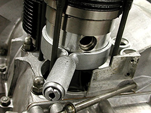
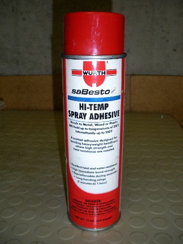